Page 26
22.10.2019
R01.43
3.5.2 Electrical Connection
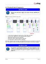
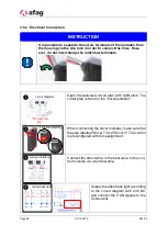
Open the delivered circuit plan with USB stick. The
circuit plan is found in the "documentation".
When connecting the driver modules, make sure that
they are labelled "Driver 1" and "Driver 2". The control
is preconfigured with this assignment.
Connect the aflex cable, in the best case, to the con-
trol modules via a terminal strip.
Supply the aflex back light according
to the circuit diagram with 24V DC
and connect the CAN signals to the
ControlUnit.
INSTRUCTION
It is possible to separate the screw terminals of the modules from
the housing via the clip lock in order to connect the lines. How-
ever, do not interchange the individual terminals.
❶
circuit diagram
"Documenta-
tion"
❷
consider labelling
or
Driver 1
Driver 2
wiring actuators
❸
wiring back light
❹

