Page 76
22.10.2019
R01.43
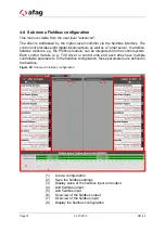
Overview of the fieldbus input (7)
Display the fieldbus input.
Display the fieldbus configuration (8)
Display the fieldbus configuration.
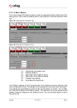
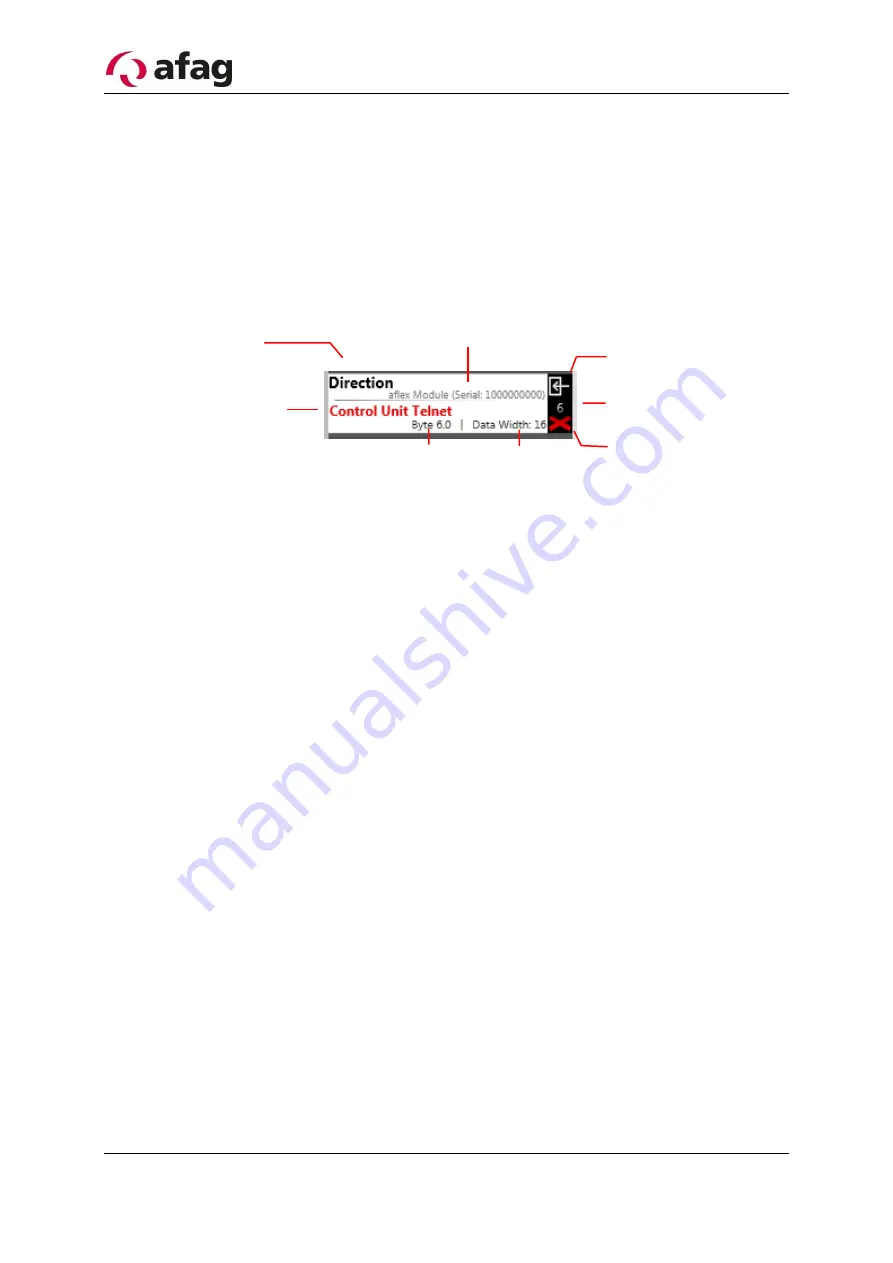
Figure 62: Structure of the inputs/outputs
(1)
Fieldbus interface
(2)
Command identification addressed parameters
(3)
Addressed control module whose parameter is controlled
(4)
Symbol for fieldbus input
(5)
Identification number of the fieldbus input
(6)
Delete the fieldbus input
(7)
Data range of the fieldbus input
(8)
Byte offset of the fieldbus input
Fieldbus interface/Fieldbus Device (1)
The fieldbus interface defines the interface via which the higher-level control is com-
municated.
Parameter/Target Field (2)
Defines which parameter is described via the fieldbus input.
Addressed control module / Target device (3)
Defines the control module/software module whose parameter is changed. In this ex-
ample, the "direction" of the aflex software module is changed with the serial number
1000000000.
Data range of the fieldbus input (7)
The data range of the parameters are variable and can thus be adapted to the fieldbus.
The selected data range is internally converted into the original data range, which is
displayed in brackets when selected. If a parameter with the native data range of 32
2
1
8
7
5
4
6
6

