Release: 02.0
2017-01-13
Page 21
Connection of the control
All modules of the control are mounted on a profile rail with BackSideBus.
The modules are fixed via end terminals and the terminating resistors of the BackSide-
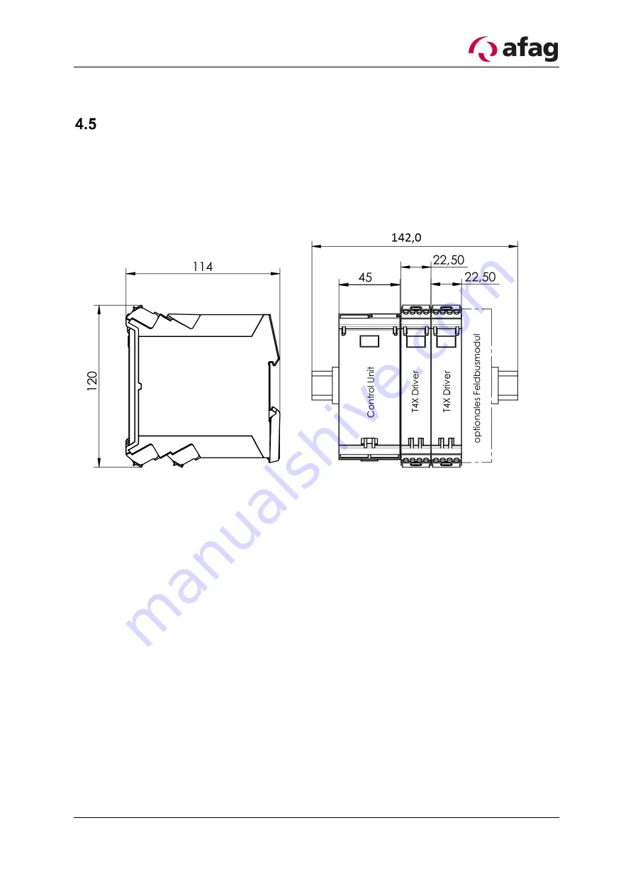
Bus are thus protected. Below is a drawing of the controller. The profile rail is delivered
with a length of 142.0 mm, the BackSideBus with a length of 123.0 mm.
Figure 9: Drawing Control modules
The control is sent in the mounted state; it is possible to install the profile rail in the
control cabinet without dismantling. Alternatively, the control modules can be disman-
tled. For subsequent reassembly, observe the following procedure:
1. Mount the profile rail in the control cabinet, the screw head height must not ex-
ceed 3.8 mm.
2. Fasten the bus circuit board using the corresponding circuit board cover.
3. If necessary, remove the protective film from the conductor tracks
4. Now place the individual control modules on the profile rail. Make sure that the
housings are not jammed and the contacts to the BackSideBus are not bent.
5. Mount the profile rail end brackets TS35 so that the terminating resistors of the
bus rail are protected and the control modules are fixed.
6. Use the circuit diagram found in the appendix of the aflex system to connect the
control modules.


