background image


Assembly instructions

 DE  


EPS Handling systems  


Date 08.09.2021  

  Version 2.0 

1–112


Assembly and operating instructions 


EPS Handling Systems (electrical) 


EPS mini YZ 

EPS midi YZ 

EPS maxi YZ 

EPS giga YZ 

EPS tera YZ 


EPS mini XZ 

EPS midi XZ 

EPS maxi XZ 


EPS mini XYZ 

EPS midi XYZ 

EPS maxi XYZ 


EPS mini gantry XXYZ 

EPS midi gantry XXYZ 

EPS maxi gantry XXYZ 


EPS mini gantry s 

EPS midi gantry s 

EPS maxi gantry s 


EPS mini gantry h 

EPS midi gantry h 

EPS maxi gantry h 

Translation of the Original Assembly Instructions EN


Summary of Contents for EPS giga YZ

Page 1: ...mini YZ EPS midi YZ EPS maxi YZ EPS giga YZ EPS tera YZ EPS mini XZ EPS midi XZ EPS maxi XZ EPS mini XYZ EPS midi XYZ EPS maxi XYZ EPS mini gantry XXYZ EPS midi gantry XXYZ EPS maxi gantry XXYZ EPS mini gantry s EPS midi gantry s EPS maxi gantry s EPS mini gantry h EPS midi gantry h EPS maxi gantry h Translation of the Original Assembly Instructions EN ...

Page 2: ... the state of the art Due to the constant technical development and improvement of our products we reserve the right to make technical changes at any time Updates of our documentations Unlike the printed documents our digital instructions manuals product data sheets and catalogues are being continuously updated on our website Please keep in mind that the digital documents on our website are always...

Page 3: ... Personal protective equipment PPE 13 2 7 Changes and modifications 13 2 8 General hazards residual risks 14 2 8 1 General hazards at the workplace 14 2 8 2 Danger due to electricity 14 2 8 3 Danger due to strong magnetic fields 15 2 8 4 Danger due to pneumatics 15 2 8 5 Danger due to high temperatures 15 2 8 6 Mechanical hazards 15 3 Technical data 16 3 1 EPS System mini YZ 16 3 1 1 Dimensioned d...

Page 4: ... drawing EPS mini XYZ 40 3 9 2 Technical data EPS mini XYZ 41 3 9 3 Module loads EPS mini XYZ 42 3 10 EPS System midi XYZ 43 3 10 1 Dimensioned drawing EPS midi XYZ 43 3 10 2 Technical data EPS midi XYZ 44 3 10 3 Module loads EPS midi XYZ 45 3 11 EPS System maxi XYZ 46 3 11 1 Dimensioned drawing EPS maxi XYZ 46 3 11 2 Technical data EPS maxi XYZ 47 3 11 3 Module loads EPS maxi XYZ 48 3 12 EPS mini...

Page 5: ...try h 71 3 19 3 Module loads EPS midi gantry h 72 3 20 EPS maxi gantry h 73 3 20 1 Dimensioned drawing EPS maxi gantry h 73 3 20 2 Technical data EPS maxi gantry h 74 3 20 3 Module loads EPS maxi gantry h 75 3 21 Overview of power supplies 76 4 Transport packaging and storage 77 4 1 Safety instructions for transport 77 4 2 Transport 77 4 3 Packaging 77 4 4 Storage 78 5 Installation assembly and se...

Page 6: ...bleshooting 99 7 2 Fault causes and remedy 99 8 Maintenance and repair 100 8 1 General notes 100 8 2 Safety instructions for Maintenance and Repair 100 8 3 Maintenance activities and maintenance intervals 101 8 3 1 Overview of the maintenance points 101 8 3 2 Further maintenance 101 8 4 Spare parts 102 8 4 1 Motor cable Designation Axes Controller Application 102 8 4 2 Motor cable 103 8 4 3 Servo ...

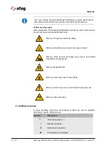
Page 7: ...ling system The illustrations in this manual shall provide you with a basic understanding of the module and may vary from the actual design of your module 1 2 Explanation of symbols The safety notes are marked by a pictogram and a signal word The safety notes describe the extent of the hazard DANGER Danger This safety note indicates an imminently hazardous situation which if not avoided will resul...

Page 8: ...ealth risks Warning Dangerous electrical voltage Warning hot surfaces can cause burns upon contact Warning Risk of hand and finger injury due to uncontrolled movements of components Warning Magnetic field Warning back injury due to heavy lifting Warning Risk of injury as a result of parts being flung out Warning high noise levels 1 3 Additional symbols In these assembly instructions the following ...

Page 9: ...ther claims are excluded The warranty shall expire in the following cases Improper use of the handling system Non observance of the instructions regarding assembly commissioning operation and maintenance of the module Improper assembly commissioning operation and maintenance Repairs and design changes carried out without prior technical instructions of Afag Removing the serial number from the prod...

Page 10: ...ns given in this instructions manual may result in serious hazards 2 2 Intended use EPS handling systems are designed for use in automation systems and are used exclusively for moving workpieces The pneumatic modules are exclusively intended for operation by means of compressed air 4 7 bar The electric axes are designed exclusively for operation with original LinMot components controller cables EP...

Page 11: ... only personnel who have the necessary professional qualifications and experience are familiar with the basic rules regarding occupational safety and accident prevention have been instructed in the correct handling of the EPS have read and understood these assembly instructions The operating company is also required to monitor on an ongoing basis that the personnel work safely considering any pote...

Page 12: ...ersonnel may be permitted to carry out the described activities on the EPS handling system Persons whose ability to react is restricted due to the intake of medication or the like must not interact with the EPS handling system These installation instructions are intended for skilled personnel installers system integrators maintenance personnel technicians electricians and operating personnel The f...

Page 13: ...und on the personal protective equipment Personal protective equipment and the respective mandatory signs Protective clothing is a close fitting clothing specifically designed to protect personnel from hazards during work Protective gloves are specifically designed to protect the personnel against hand injuries such as cuts abrasion burns Safety shoes are specifically designed to protect the perso...

Page 14: ...r third parties on the EPS system itself property damage Always keep the assembly instructions ready at hand at the workplace Please also observe the general and local regulations on accident prevention and environmental protection the safety information sheet for the EPS system 2 8 2 Danger due to electricity CAUTION Risk of injuries due to uncontrolled parts movements Incorrect control of the dr...

Page 15: ...se serious or fatal injuries Work on the machine s electrical equipment may only be performed by skilled electrician or trained personnel under the supervision of a skilled electrician in accordance with all relevant electrical regulations CAUTION Personal injury caused by hot surfaces During continuous operation of the EPS handling system the surface heats up Avoid direct contact if the system ha...

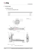
Page 16: ...ical data 16 112 Assembly instructions EN EPS Handling systems Date 08 09 2021 Version 2 0 3 Technical data 3 1 EPS System mini YZ 3 1 1 Dimensioned drawing EPS mini YZ Fig 1 Dimensioned drawing EPS mini YZ ...

Page 17: ...Technical data Assembly instructions DE EPS Handling systems Date 08 09 2021 Version 2 0 17 112 3 1 2 Technical data EPS mini YZ ...

Page 18: ...Technical data 18 112 Assembly instructions EN EPS Handling systems Date 08 09 2021 Version 2 0 3 1 3 Module loads EPS mini YZ ...

Page 19: ...Technical data Assembly instructions DE EPS Handling systems Date 08 09 2021 Version 2 0 19 112 3 2 EPS System midi YZ 3 2 1 Dimensioned drawing EPS midi YZ Fig 2 Dimensioned drawing EPS midi YZ ...

Page 20: ...Technical data 20 112 Assembly instructions EN EPS Handling systems Date 08 09 2021 Version 2 0 3 2 2 Technical data EPS midi YZ ...

Page 21: ...Technical data Assembly instructions DE EPS Handling systems Date 08 09 2021 Version 2 0 21 112 3 2 3 Module loads EPS midi YZ ...

Page 22: ...Technical data 22 112 Assembly instructions EN EPS Handling systems Date 08 09 2021 Version 2 0 3 3 EPS System maxi YZ 3 3 1 Dimensioned drawing EPS maxi YZ Fig 3 Dimensioned drawing EPS maxi YZ ...

Page 23: ...Technical data Assembly instructions DE EPS Handling systems Date 08 09 2021 Version 2 0 23 112 3 3 2 Technical data EPS maxi YZ ...

Page 24: ...Technical data 24 112 Assembly instructions EN EPS Handling systems Date 08 09 2021 Version 2 0 3 3 3 Module loads EPS maxi YZ ...

Page 25: ...Technical data Assembly instructions DE EPS Handling systems Date 08 09 2021 Version 2 0 25 112 3 4 EPS System giga YZ 3 4 1 Dimensioned drawing EPS giga YZ Fig 4 Dimensioned drawing EPS giga YZ ...

Page 26: ...Technical data 26 112 Assembly instructions EN EPS Handling systems Date 08 09 2021 Version 2 0 3 4 2 Technical data EPS giga YZ ...

Page 27: ...Technical data Assembly instructions DE EPS Handling systems Date 08 09 2021 Version 2 0 27 112 3 4 3 Module loads EPS giga YZ ...

Page 28: ...Technical data 28 112 Assembly instructions EN EPS Handling systems Date 08 09 2021 Version 2 0 3 5 EPS System tera YZ 3 5 1 Dimensioned drawing EPS tera YZ Fig 5 Dimensioned drawing EPS tera YZ ...

Page 29: ...Technical data Assembly instructions DE EPS Handling systems Date 08 09 2021 Version 2 0 29 112 3 5 2 Technical data EPS tera YZ ...

Page 30: ...Technical data 30 112 Assembly instructions EN EPS Handling systems Date 08 09 2021 Version 2 0 3 5 3 Module loads EPS tera YZ ...

Page 31: ...Technical data Assembly instructions DE EPS Handling systems Date 08 09 2021 Version 2 0 31 112 3 6 EPS System mini XZ 3 6 1 Dimensioned drawing EPS mini XZ Fig 6 Dimensioned drawing EPS mini XZ ...

Page 32: ...Technical data 32 112 Assembly instructions EN EPS Handling systems Date 08 09 2021 Version 2 0 3 6 2 Technical data EPS mini XZ ...

Page 33: ...Technical data Assembly instructions DE EPS Handling systems Date 08 09 2021 Version 2 0 33 112 3 6 3 Module loads EPS mini XZ ...

Page 34: ...Technical data 34 112 Assembly instructions EN EPS Handling systems Date 08 09 2021 Version 2 0 3 7 EPS System midi XZ 3 7 1 Dimensioned drawing EPS midi XZ Fig 7 Dimensioned drawing EPS midi XZ ...

Page 35: ...Technical data Assembly instructions DE EPS Handling systems Date 08 09 2021 Version 2 0 35 112 3 7 2 Technical data EPS midi XZ ...

Page 36: ...Technical data 36 112 Assembly instructions EN EPS Handling systems Date 08 09 2021 Version 2 0 3 7 3 Module loads EPS midi XZ ...

Page 37: ...Technical data Assembly instructions DE EPS Handling systems Date 08 09 2021 Version 2 0 37 112 3 8 EPS System maxi XZ 3 8 1 Dimensioned drawing EPS maxi XZ Fig 8 Dimensioned drawing EPS maxi XZ ...

Page 38: ...Technical data 38 112 Assembly instructions EN EPS Handling systems Date 08 09 2021 Version 2 0 3 8 2 Technical data EPS maxi XZ ...

Page 39: ...Technical data Assembly instructions DE EPS Handling systems Date 08 09 2021 Version 2 0 39 112 3 8 3 Module loads EPS maxi XZ ...

Page 40: ...Technical data 40 112 Assembly instructions EN EPS Handling systems Date 08 09 2021 Version 2 0 3 9 EPS System mini XYZ 3 9 1 Dimensioned drawing EPS mini XYZ Fig 9 Dimensioned drawing EPS mini XYZ ...

Page 41: ...Technical data Assembly instructions DE EPS Handling systems Date 08 09 2021 Version 2 0 41 112 3 9 2 Technical data EPS mini XYZ ...

Page 42: ...Technical data 42 112 Assembly instructions EN EPS Handling systems Date 08 09 2021 Version 2 0 3 9 3 Module loads EPS mini XYZ ...

Page 43: ...Technical data Assembly instructions DE EPS Handling systems Date 08 09 2021 Version 2 0 43 112 3 10 EPS System midi XYZ 3 10 1 Dimensioned drawing EPS midi XYZ Fig 10 Dimensioned drawing EPS midi XYZ ...

Page 44: ...Technical data 44 112 Assembly instructions EN EPS Handling systems Date 08 09 2021 Version 2 0 3 10 2 Technical data EPS midi XYZ ...

Page 45: ...Technical data Assembly instructions DE EPS Handling systems Date 08 09 2021 Version 2 0 45 112 3 10 3 Module loads EPS midi XYZ ...

Page 46: ...Technical data 46 112 Assembly instructions EN EPS Handling systems Date 08 09 2021 Version 2 0 3 11 EPS System maxi XYZ 3 11 1 Dimensioned drawing EPS maxi XYZ Fig 11 Dimensioned drawing EPS maxi XYZ ...

Page 47: ...Technical data Assembly instructions DE EPS Handling systems Date 08 09 2021 Version 2 0 47 112 3 11 2 Technical data EPS maxi XYZ ...

Page 48: ...Technical data 48 112 Assembly instructions EN EPS Handling systems Date 08 09 2021 Version 2 0 3 11 3 Module loads EPS maxi XYZ ...

Page 49: ...l data Assembly instructions DE EPS Handling systems Date 08 09 2021 Version 2 0 49 112 3 12 EPS mini gantry XXYZ 3 12 1 Dimensioned drawing EPS mini gantry XXYZ Fig 12 Dimensioned drawing EPS mini gantry XXYZ ...

Page 50: ...Technical data 50 112 Assembly instructions EN EPS Handling systems Date 08 09 2021 Version 2 0 3 12 2 Technical data EPS mini gantry XXYZ ...

Page 51: ...Technical data Assembly instructions DE EPS Handling systems Date 08 09 2021 Version 2 0 51 112 3 12 3 Module loads EPS mini gantry XXYZ ...

Page 52: ...l data 52 112 Assembly instructions EN EPS Handling systems Date 08 09 2021 Version 2 0 3 13 EPS midi gantry XXYZ 3 13 1 Dimensioned drawing EPS midi gantry XXYZ Fig 13 Dimensioned drawing EPS midi gantry XXYZ ...

Page 53: ...Technical data Assembly instructions DE EPS Handling systems Date 08 09 2021 Version 2 0 53 112 3 13 2 Technical data EPS midi gantry XXYZ ...

Page 54: ...Technical data 54 112 Assembly instructions EN EPS Handling systems Date 08 09 2021 Version 2 0 3 13 3 Module loads EPS midi gantry XXYZ ...

Page 55: ...l data Assembly instructions DE EPS Handling systems Date 08 09 2021 Version 2 0 55 112 3 14 EPS maxy gantry XXYZ 3 14 1 Dimensioned drawing EPS maxi gantry XXYZ Fig 14 Dimensioned drawing EPS maxi gantry XXYZ ...

Page 56: ...Technical data 56 112 Assembly instructions EN EPS Handling systems Date 08 09 2021 Version 2 0 3 14 2 Technical data EPS maxi XYZ ...

Page 57: ...Technical data Assembly instructions DE EPS Handling systems Date 08 09 2021 Version 2 0 57 112 3 14 3 Module loads EPS maxi gantry XXYZ ...

Page 58: ...hnical data 58 112 Assembly instructions EN EPS Handling systems Date 08 09 2021 Version 2 0 3 15 EPS mini gantry s 3 15 1 Dimensioned drawing EPS mini gantry s Fig 15 Dimensioned drawing EPS mini gantry s ...

Page 59: ...Technical data Assembly instructions DE EPS Handling systems Date 08 09 2021 Version 2 0 59 112 3 15 2 Technical data EPS mini gantry s ...

Page 60: ...Technical data 60 112 Assembly instructions EN EPS Handling systems Date 08 09 2021 Version 2 0 3 15 3 Module loads EPS mini gantry s ...

Page 61: ...hnical data Assembly instructions DE EPS Handling systems Date 08 09 2021 Version 2 0 61 112 3 16 EPS midi gantry s 3 16 1 Dimensioned drawing EPS midi gantry s Fig 16 Dimensioned drawing EPS midi gantry s ...

Page 62: ...Technical data 62 112 Assembly instructions EN EPS Handling systems Date 08 09 2021 Version 2 0 3 16 2 Technical data EPS midi gantry s ...

Page 63: ...Technical data Assembly instructions DE EPS Handling systems Date 08 09 2021 Version 2 0 63 112 3 16 3 Module loads EPS midi gantry s ...

Page 64: ...hnical data 64 112 Assembly instructions EN EPS Handling systems Date 08 09 2021 Version 2 0 3 17 EPS maxi gantry s 3 17 1 Dimensioned drawing EPS maxi gantry s Fig 17 Dimensioned drawing EPS maxi gantry s ...

Page 65: ...Technical data Assembly instructions DE EPS Handling systems Date 08 09 2021 Version 2 0 65 112 3 17 2 Technical data EPS maxi gantry s ...

Page 66: ...Technical data 66 112 Assembly instructions EN EPS Handling systems Date 08 09 2021 Version 2 0 3 17 3 Module loads EPS maxi gantry s ...

Page 67: ...hnical data Assembly instructions DE EPS Handling systems Date 08 09 2021 Version 2 0 67 112 3 18 EPS mini gantry h 3 18 1 Dimensioned drawing EPS mini gantry h Fig 18 Dimensioned drawing EPS mini gantry h ...

Page 68: ...Technical data 68 112 Assembly instructions EN EPS Handling systems Date 08 09 2021 Version 2 0 3 18 2 Technical data EPS mini gantry h ...

Page 69: ...Technical data Assembly instructions DE EPS Handling systems Date 08 09 2021 Version 2 0 69 112 3 18 3 Module loads EPS mini gantry h ...

Page 70: ...hnical data 70 112 Assembly instructions EN EPS Handling systems Date 08 09 2021 Version 2 0 3 19 EPS midi gantry h 3 19 1 Dimensioned drawing EPS midi gantry h Fig 19 Dimensioned drawing EPS midi gantry h ...

Page 71: ...Technical data Assembly instructions DE EPS Handling systems Date 08 09 2021 Version 2 0 71 112 3 19 2 Technical data EPS midi gantry h ...

Page 72: ...Technical data 72 112 Assembly instructions EN EPS Handling systems Date 08 09 2021 Version 2 0 3 19 3 Module loads EPS midi gantry h ...

Page 73: ...hnical data Assembly instructions DE EPS Handling systems Date 08 09 2021 Version 2 0 73 112 3 20 EPS maxi gantry h 3 20 1 Dimensioned drawing EPS maxi gantry h Fig 20 Dimensioned drawing EPS maxi gantry h ...

Page 74: ...Technical data 74 112 Assembly instructions EN EPS Handling systems Date 08 09 2021 Version 2 0 3 20 2 Technical data EPS maxi gantry h ...

Page 75: ...Technical data Assembly instructions DE EPS Handling systems Date 08 09 2021 Version 2 0 75 112 3 20 3 Module loads EPS maxi gantry h ...

Page 76: ...utomatic switching 3x340 550 VAC 50 60 Hz 3x230 400 480 VAC 50 60 Hz Secondary voltage 54 80 VDC adjustable 54 80 VDC adjustable 72 VDC Output power 480 W 960 W 1500 W Power consumption 600 W 1100 W 1500 W Max power loss 54 W 91 W 110 W Peak output current 0 5 s 10 A 27 A 50 A Rated current 240 VAC 4 5 A 120 VAC 9 A 380 VAC 3 1 A 3x230 VAC 3 5 A 400 VAC 2 A 480 VAC 1 7 A Efficiency 88 91 5 85 at n...

Page 77: ... the EPS system must be packed in such a way that it is protected against shocks and dust The packaging materials used are mainly cardboard and paper or PE film These are materials that can be recycled worldwide If the packaging is returned to us carriage paid Afag will take it back free of charge and dispose of it properly NOTICE Risk of damage to property EPS systems are precision mechanical dev...

Page 78: ... following Store the EPS system in the transport packaging Do not store the servo gripper outdoors or expose it to weather conditions The storage space must be dry and dust free Room temperature of the storage space 0 50 C Relative air humidity 90 non condensing Clean the EPS and protect the blank metal parts against corrosion using the appropriate means Protect the EPS system from dirt and dust ...

Page 79: ...stallation on the part of the operator 5 1 Safety instructions for installation and assembly Also observe the safety instructions in chapter 2 Safety instructions in this manual CAUTION Personal injury caused by hot surfaces High surface temperatures up to 60 C can occur on the EPS systems There is a risk of injury and damage to property No temperature sensitive parts such as cables or electronic ...

Page 80: ... RA 40 2 4x O ring 2 5x0 62 NBR70 2x centring bushing Ø7x3 2x centring bushing Ø5x2 5 ES20 4x Ø 7h6 centring bushing 8x screw M4 ES30 4x Ø 9h6 centring bushing 4x screw M5 ES40 Centring bushing Ø12x4 8 PEL20 2x Ø 9h6 centring bushing 4x screw M6 2x Ø 7h6 centring bushing 4x screw M4 2x Ø 5h6 centring bushing 4x screw M3 2x cylindrical pin 5m6 Mounting block for PEL20 PDL30_PDL40 M8 screw PDL30 2x ...

Page 81: ...s set by clamping the MagSpring stator with the slide fully retracted Inverted installation position With the installation position reversed the dimension SP 35 mm is set by clamping the MagSpring stator with the slide fully extended The dimension L of the MagSpring extension depends on the stroke of the module used 5 3 2 Weight compensation with pneumatic cylinder Please observe the corresponding...

Page 82: ... 232 Digital I Os Max power consumption 30 W 30 W 30 W Protect class IP 20 IP 20 IP 20 Operating temperature 0 40 C 0 40 C 0 40 C Ground 1 5 kg 1 5 kg 1 5 kg Distance between controllers 20 mm left right 50 mm bottom top 20 mm left right 50 mm bottom top 20 mm left right 50 mm bottom top Fuse protection 72 V supply 16 AT 16 AT 16 AT Fuse protection 24 V supply 3 AT 3 AT 3 AT Fig 23 Axis controller...

Page 83: ... bottom top 20 mm left right 50 mm bottom top 20 mm left right 50 mm bottom top 20 mm left right 50 mm bottom top Fuse protection 72 V supply 16 AT 16 AT 16 AT 16 AT Fuse protection 24 V supply 3 AT 3 AT 3 AT 3 AT Technical data C1250 SC XC C1250 SE XC Logistics supply 24 VDC 24 VDC Motor power supply 24 72 VDC 24 72 VDC Max motor output current at 72 V 25 A 25 A Bus systems Interfaces Sercos III ...

Page 84: ...D X2 Motor phases X3 Motor Signals X33 Safety relay optional for S1 version X4 8 Quick stop X4 7 Reference sensor optional X4 2 Logic voltage supply 24 VDC X4 1 Logic voltage supply GND DANGER Danger when the safety door is open There is a high risk of injury when the safety door is open For the C12xx controller the safety relay input X33 must be deactivated or the power supply unit 72 V must be d...

Page 85: ... kg Distance between controllers 20 mm left right 50 mm bottom top 20 mm left right 50 mm bottom top 20 mm left right 50 mm bottom top 20 mm left right 50 mm bottom top Fuse protection 72 V supply 20 AT 20 AT 20 AT 20 AT Fuse protection 24 V supply 2 AT 2 AT 2 AT 2 AT Technical data E1250 IP UC E1250 PN UC E1250 SC UC Logistics supply 24 VDC 24 VDC 24 VDC Motor power supply 24 72 VDC 24 72 VDC 24 ...

Page 86: ... PGND Motor power supply GND X2 Motor phases X3 Motor Signals X4 12 Safety voltage enable X4 11 Quick stop X4 7 Reference sensor optional X4 2 Logic voltage supply 24 VDC X4 1 Logic voltage supply GND DANGER Danger when the safety door is open There is a high risk of injury when the safety door is open With the E12xx controller the power supply unit 72 V must be safely disconnected on the primary ...

Page 87: ...or combinations Connector on the axle Connector on the controller R connector Insert Electric slide ES20 Portal axis PEL20 Rotary axis SE20 D connector Insert C connector Insert Electric slide ES30 Portal axis PEL30 Portal axis PDL30 Portal axis PDL40 Portal axis PDL40 HC Rotary axis SE30 W connector Insert Controller E12xx UC Y connector Insert Controller C11xx XC Controller C12xx XC ...

Page 88: ...6 Connector assignment encoder on the controller Controller C1xxx and E12xx series PIN Function Colour 1 5V pink 2 A sin yellow 3 B cos grey 4 Z data white 5 GND red blue violet 6 Free 7 Free 8 Clock Green 9 A sin Black 10 B cos Red 11 Z Data blue 12 Free 13 Free 14 Free 15 Clock grey pink Housing Screen outer screen ...

Page 89: ...in 16520816 The power strip offers three essential functions Connecting the sensors of the periphery Display 24 V supply Display of the switching states of the sensors Suitable Angle plug series 768 3 pin M8x1 16520057 Connection cable 12 pin angled socket 10m 16520686 Connection cable 12 pin angled socket 15m 16520833 Pin assignment of connector strip Assignment of the sockets 3 pole Function PIN...

Page 90: ...king area of the EPS Due to the decentralised control system the operator of the EPS must not necessarily stand next to the module during operation so that he may not have a complete view of the working area Persons in the working area may be injured During operation ensure a good overview of the working area Unauthorised persons are not allowed in the work area CAUTION Risk of injuries due to unc...

Page 91: ... positions on electric axes chapter 6 4 2 3 Set the damping speeds on the pneumatic modules chapter 6 4 3 4 Set the external position measuring system chapter 6 4 4 The preliminary settings for commissioning are completed 6 3 Commissioning of the modules Proceed carefully and follow the instructions step by step when commissioning the modules for the first time 1 Observe the permissible technical ...

Page 92: ...ntrollers with which the maximum speed acceleration and the target position can be specified These programmes are stored on the CD supplied or can be downloaded from https www afag com de service support tools linmot html CAUTION Danger of material damage and personal injury due to improperly performed adjustment work Improperly carried out activities can result in considerable material damage and...

Page 93: ... 20 1 7 15 15 SE30 x 50 x 0 84 30 30 0 84 20 20 SE30 x 30 x 1 7 20 20 1 7 15 15 RA 40 x x 50 x x 0 84 30 30 0 84 20 20 RA 40 x x 30 x x 1 7 20 20 1 7 15 15 ES20 50 SL 7 3 120 120 3 15 15 50 0 ES20 100 SL 5 3 80 80 3 10 10 100 0 ES20 200 5 3 60 60 3 10 10 200 0 ES20 300 5 3 40 40 3 10 10 300 0 ES30 050 SL 3 9 80 80 2 15 15 50 0 ES30 100 SL 3 9 80 80 2 15 15 100 0 ES30 100 3 9 80 80 2 15 15 100 0 ES...

Page 94: ...0 0 PEL20 060 5 3 80 80 3 10 10 60 0 PEL20 130 5 3 80 80 3 10 10 130 0 PEL20 190 5 3 80 80 3 10 10 190 0 PEL20 290 5 3 80 80 3 10 10 290 0 PEL20 470 5 3 80 80 3 10 10 470 0 PEL20 560 5 3 80 80 3 10 10 560 0 PDL30 90 D19 3 9 80 80 2 15 15 90 0 PDL30 150 D19 3 9 80 80 2 15 15 150 0 PDL30 250 D19 3 9 80 80 2 15 15 250 0 PDL30 350 D19 3 9 80 80 2 15 15 350 0 PDL30 450 D19 3 9 80 80 2 15 15 450 0 PDL30...

Page 95: ...0 580 D28 3 80 80 2 15 15 580 0 PDL40 670 D28 3 80 80 2 15 15 670 0 PDL40 880 D28 3 80 80 2 15 15 880 0 PDL40 1060 D28 3 80 80 2 15 15 1060 0 PDL40 1270 D28 3 80 80 2 15 15 1270 0 PDL40 1480 D28 3 80 80 2 15 15 1480 0 PDL40 1660 D28 3 80 80 2 15 15 1660 0 PDL40HP 0200 D27 2 1 80 80 1 5 15 15 200 0 PDL40HP 0320 D27 2 1 80 80 1 5 15 15 320 0 PDL40HP 0410 D27 2 1 80 80 1 5 15 15 410 0 PDL40HP 0160 D2...

Page 96: ...eaching in jog mode Procedure for manual teaching 1 Reference drive 2 Add or subtract value to the current position Can be programmed via relative command 3 The existing module for absolute positioning can be converted into a module for relative positioning by changing a variable Teaching in jog mode is completed 3 Set up with reduced speed Please observe the associated instructions for safely red...

Page 97: ...s on the setting 1 Mount the sensor parallel to the belt using a feeler gauge Value for the distance between sensor and belt see table Sensor type Distance min Distance max Recommend MSK1000 0 1mm 0 2mm 0 1mm MSA501 0 1mm 1 5mm 0 5mm 2 Adjust the distance between the sensor and the belt The desired distance is set NOTICE Risk of damage to property Incorrectly set end position damping can cause dam...

Page 98: ...scribed in the LinMot manual Set the Home Position to 0 mm 2 Reference the axis 3 De energise the axis by removing the switch ON bit 4 Press the axle by hand against the mechanical stop 5 Adjust the actual position by moving the sensor so that the distance to be set appears with a negative sign e g Home Position 0 mm Actual Position 0 5 mm If the home position is set to a different value the corre...

Page 99: ... injuries Work on the machine s electrical equipment may only be performed by skilled electrician or trained personnel under the supervision of a skilled electrician in accordance with all relevant electrical regulations WARNING Danger of injury due to faulty troubleshooting Poorly performed troubleshooting work can lead to serious injuries and damage to property Only use trained specialist person...

Page 100: ...n electrical components is required ensure that the work is carried out properly failure to do so will cause serious or fatal injuries All work on the module must be carried out with the power supply cut off Switch off the power supply and secure it against being switched on again DANGER Risks by the pneumatic system If work on electrical components is required ensure that the work is carried out ...

Page 101: ...No Maintenance point Maintenance work Interval System On Off Remarks 1 EPS handling system Cleaning and checking As required Off Clean the servo gripper with a dry lint free cloth Do not spray the EPS with water do not use aggressive cleaning agents Carry out a visual inspection of the EPS system 2 Pneumatic cylinder weight compensation if installed Check As required Off 2 Pneumatic cylinder If a ...

Page 102: ... W R 8 Motor cable M20 8m 0 2 1 x x x x x x X KR05 W R 8 Motor cable M20 8m 0 2 2 x x x x x x x X K05 Y R 8 Motor cable M16 8m 0 1 X x x x x x X KS05 Y R 8 Motor cable M16 8m 0 1 1 x x x x x x X KR05 Y R 8 Motor cable M16 8m 0 1 2 x x x x x x x X K15 W C 8 Motor cable M24 8m 0 2 X x x x x X x X KS10 W C 8 Motor cable M22 8m 0 2 1 x x x x x x x X KR10 W C 8 Motor cable M22 8m 0 2 2 x x x x x x x x ...

Page 103: ...4m 0 0 1 50427024 Extension M17 6m 0 0 1 50463087 Extension M17 2m 0 0 2 50463085 Extension M17 4m 0 0 2 50463086 Motor cable M20 4m 0 2 X 50463088 Motor cable M20 6m 0 2 X 50463090 Motor cable M20 8m 0 2 X 50463092 Motor cable M20 4m 0 2 1 50463089 Motor cable M20 6m 0 2 1 50463091 Motor cable M20 8m 0 2 1 50463093 Motor cable M21 4m 0 0 X 50463094 Motor cable M21 6m 0 0 X 50463096 Motor cable M2...

Page 104: ...cle no External position measuring system ES20 050mm 50427547 External position measuring system ES20 100mm 50427560 External position measuring system ES20 200mm 50427573 External position measuring system ES20 300mm 50427586 External position measuring system ES30 050mm 50429204 External position measuring system ES30 100mm 50429217 External position measuring system ES30 200mm 50429230 External...

Page 105: ...N 50N for 200 mm stroke 50430390 MagSpring rotor ML01 12x290 240 20 Force 22N 60N for 200 mm stroke 50430391 MagSpring rotor ML01 12x370 320 10 Force 11N 40N for 300 mm stroke 50430392 MagSpring rotor ML01 12x370 320 15 Force 17N 50N for 300 mm stroke 50430393 MagSpring rotor ML01 12x370 320 20 Force 22N 60N for 300 mm stroke 50430395 MagSpring stator MS01 20x60 50 Force 11 22N for 50 mm stroke 50...

Page 106: ...Information on proper disposal can be obtained from the responsible local authorities WARNING Risk of injury due to improper decommissioning and disposal Improperly carried out activities can result in considerable material damage and serious injury Only use trained specialist personnel to carry out the activities Disconnect the media supply before dismounting the module Only remove the EPS system...

Page 107: ... 1 3 1 1 5 1 3 2 1 3 4 und 1 5 1 Harmonised standards applied in particular 2014 30 EU Electromagnetic Compatibility Directive EMC 2014 35 EU Low Voltage Directive LVD EN ISO 12100 2010 Safety of machinery General design principles Risk assessment and risk reduction DIN EN 60204 1 2018 Safety of machinery Electrical equipment of machines Part 1 General requirements Note The partly completed machin...

Page 108: ...ations 9 I Instructions 8 O Obligations and liability 11 Obligations of the operating company 11 Obligations of the personnel 12 Operation 99 Operator 12 P Packaging 77 Personal protective equipment PPE 13 Personnel qualifications 12 Personnel requirements 12 Protective clothing 13 Protective gloves 13 Q Qualified electrician 12 Qualified personnel 12 R Residual risks 14 S Safety instructions 10 1...

Page 109: ... 11 Dimensioned drawing EPS maxi XYZ 46 Fig 12 Dimensioned drawing EPS mini gantry XXYZ 49 Fig 13 Dimensioned drawing EPS midi gantry XXYZ 52 Fig 14 Dimensioned drawing EPS maxi gantry XXYZ 55 Fig 15 Dimensioned drawing EPS mini gantry s 58 Fig 16 Dimensioned drawing EPS midi gantry s 61 Fig 17 Dimensioned drawing EPS maxi gantry s 64 Fig 18 Dimensioned drawing EPS mini gantry h 67 Fig 19 Dimensio...

Page 110: ...List of figures 110 112 Assembly instructions EN EPS Handling systems Date 08 09 2021 Version 2 0 ...

Page 111: ...Assembly instructions DE EPS Handling systems Date 08 09 2021 Version 2 0 111 112 ...

Page 112: ...List of figures 112 112 Assembly instructions EN EPS Handling systems Date 08 09 2021 Version 2 0 ...

Reviews: