Installation, assembly and setting
84 – 112
Assembly instructions EN
EPS Handling systems
Date 08.09.2021
Version 2.0
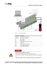
Fig. 24
Axis controller C12xx
Connection
Description
X1 PWR+
Motor power 72 VDC
X1 PGND
Motor power supply GND
X2
Motor phases
X3
Motor Signals
X33
Safety relay (optional for -S1 version)
X4.8
/Quick stop
X4.7
Reference sensor (optional)
X4.2
Logic voltage 24 VDC
X4.1
Logic voltage supply GND
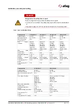
DANGER
Danger when the safety door is open!
There is a high risk of injury when the safety door is open!
For the C12xx controller, the safety relay input (X33) must be deactivated
or
the power supply unit (72 V) must be disconnected on the primary side!

