Installation, assembly and setting
Assembly instructions
DE
EPS Handling systems
Date 08.09.2021
Version 2.0
81–112
5.3 Weight compensation
With the EPS system, the weight is balanced via the MagSpring or
pneumatically unit (GWA).
Please also observe the installation instructions for the integrated modules!
5.3.1 Weight compensation with MagSpring
The following applies to both installation positions when mounting the
MagSpring:
The thread on the stator and the end of the rotor with 4 spanner flats point
downwards.
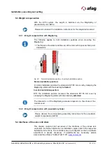
Fig. 22
Normal installation position - Inverted installation position
Normal installation position:
In normal installation position the dimension SP=35 mm is set by clamping the
MagSpring stator with the slide fully
retracted
.
Inverted installation position:
With the installation position reversed, the dimension SP=35 mm is set by
clamping the MagSpring stator with the slide fully
extended
.
The dimension L of the MagSpring extension depends on the stroke of the
module used.
5.3.2 Weight compensation with pneumatic cylinder
Please observe the corresponding assembly instructions for the pneumatic
weight compensation (GWA)!
5.4 Interfaces of the axis controllers
This chapter contains brief overviews of the interfaces of the various axis
controllers. For further information on installation, please refer to the respective
installation instructions. The controllers are pre-configured so that no software
adjustment is usually necessary. If adjustments are necessary, please

