Installation, assembly & setting
30 – 48
Assembly instructions EN
GE-25-P
Date 02.11.2021
Version 1.0
Item
Fastening the module
GE-25-P
Side B
1
Fastening screw
M3
Max. screw-in depth [mm]
6.9mm
Min. screw-in depth [mm]
6.4mm
Tightening torque [Nm]
1.2 Nm
2
Centering bushing [mm]
Ø 5 mm
Side C
5
Fastening screw
M3
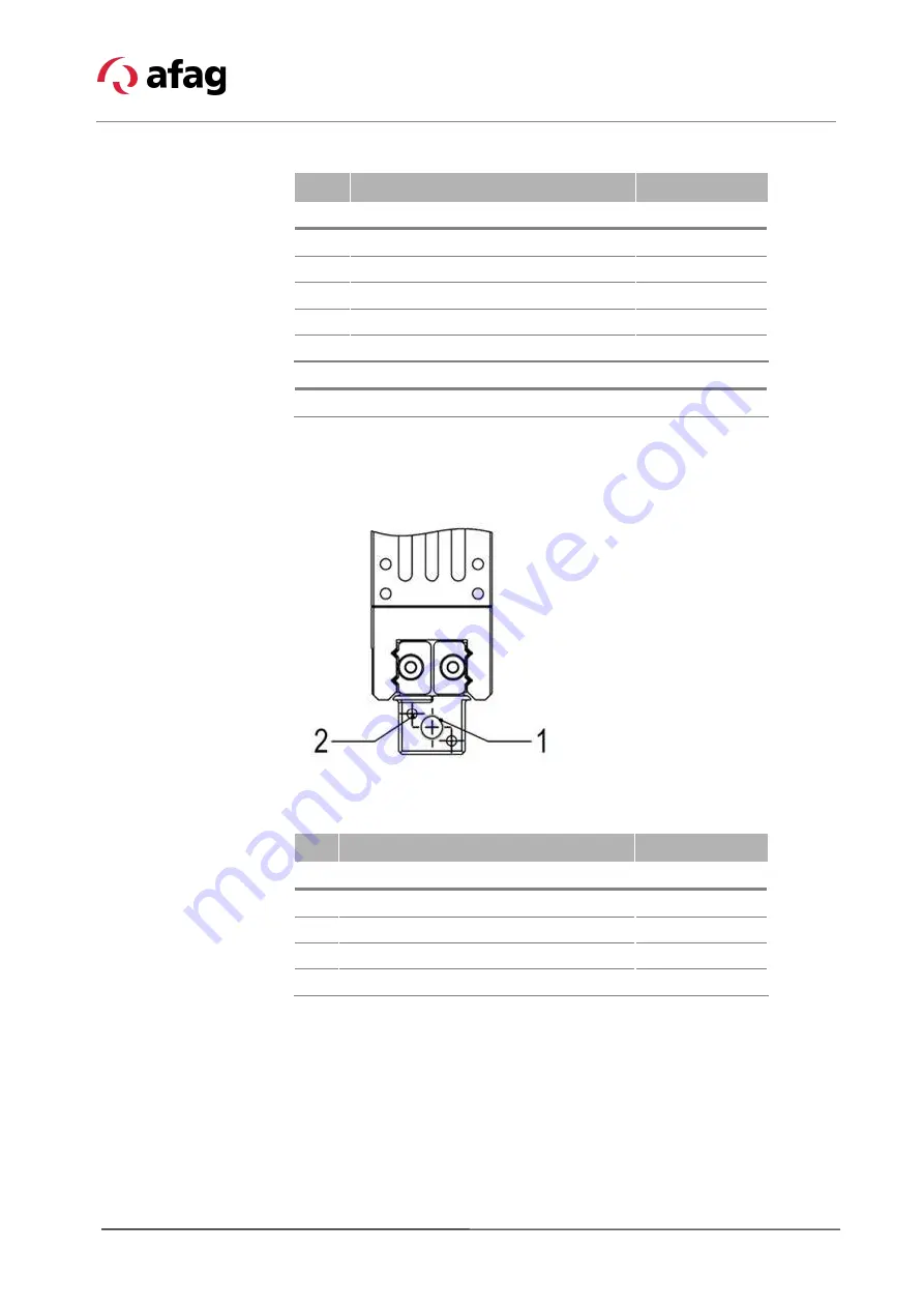
6.3.4 Connections on the base jaws (for gripper fingers)
Fig. 7
Assembly of the gripper fingers
Item Fastening the module
GE-25-P
Side A
1
Thread in base jaws
M4
Max. screw-in depth from stop surface
4mm
Max. tightening torque screws
3.1 Nm
2
Bore for cylindrical pin
Ø 1.5 mm


