background image


R05.0 


16/05/2019 

Page 15 

4


Operating instructions 

The first step in adjusting the linear feeders is always to balance the masses and then to 
adjust the natural frequency. 


4.1


Feeder track design 

The  linear  tracks  must  be  unyielding  so  that  the  transport  pulses  generated  by  the  unit 
are  fully  transferred  to  the  work  pieces  and  no  superimposed  natural  vibration  can  ad-
versely  affect  the  transport  process.  This  requirement  has  priority  over  mass  reduction 
measures. The preferred material for linear tracks is tool steel (e.g. 1.2842, 90MnCrV8). 
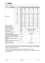
Linear  track  design  should  adhere  to  the  useful masses  specified  in  chapter  2  Table  1: 
Technical data 
and Table 4: Obligatory values for the working weight 

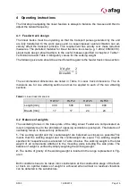
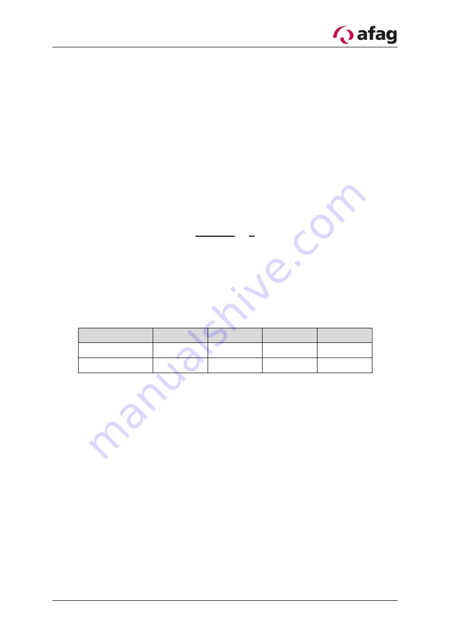
The following size ratio should be aimed for with regard to the feeder track cross-section: 


𝐻𝑒𝑖𝑔ℎ𝑡

𝐵𝑟𝑒𝑎𝑑𝑡ℎ

=

2
1


The  recommended  dimensions  are  listed  in  Table  3: 

Linear  track  dimensions

.  The  di-

mensions  are  for  one  vibrating  section  and  can  be  applied  to  each  of  the  two  vibrating 
sections. 


Table 3: 

Linear track dimensions


HLF07 

HLF12 

HLF25 

HLF50 

Length [mm] 

400 

500 

600 

800 

Breath [mm] 

17 

17 

24 

24 


4.2


Balance of weights 

The  oscillating  forces  in  the  base  plate  of  the  Afag  Linear  Feeder  are  compensated  al-
most completely due to the principle of opposing oscillations (push-pull). This balance of 
oscillating forces is however only achieved if: 

1.

  The  working  weight  and  the  counterweight  are  balanced  as  closely  as  possible.This 

means  that  the  working  weight  and  the  counterweight  are  equal.  The  working  weights 
specified for respective sizes are listed in Table 4 below. The working weight is the total 
weight  of  all  components  attached  to  the  mounting  plate  including  the  side  plate.  The 
balance of weight is verified by simply weighing the working weight. 

2.

 The centre of gravity of the working weight is located in the range represented in  Fig-

ure 3. 


Both conditions have to be taken into consideration at the construction stage of the feed-
er  track.  An  optimal  balance  of  weight  is  achieved  when  almost  no  residual  vibrations 
can be detected in the substructure. 


Summary of Contents for HLF07-M

Page 1: ...Linear feeder HLF07 M 12 M 25 M 50 M Translation of operating and installation instructions Copyright by Afag GmbH ...

Page 2: ...z 50270897 Linear feeder HLF50 230 V 50 Hz 50421880 115 V 60 Hz 50431259 Version of Documentation OI_HLF07 50_R05 0_EN Release R05 0 Date 16 05 2019 Following US patents are registered or announced Linear vibratory conveyor U S Patent No 7 784 604 Linear vibratory conveyor U S Patent No 8 051 974 Following Canadian patents are registered or announced Linear vibratory conveyor Hybrid CA Patent No 2...

Page 3: ...9 3 Assembly instructions 11 3 1 Transport 11 3 2 Installing the unit 11 3 3 Mounting of the useful mass 12 3 3 1 General 12 3 3 2 Mounting a linear track 12 3 4 Power supply 14 4 Operating instructions 15 4 1 Feeder track design 15 4 2 Balance of weights 15 4 3 Fine adjustment of natural frequency 16 4 4 Setting the air gap 18 4 5 Torques 19 5 Maintenance Instructions 20 5 1 Troubleshooting 20 5 ...

Page 4: ...n immediate threatening danger Non compliance with this information can result in death or seri ous personal injuries invalidity WARNING Indicates a possible dangerous situation Non compliance with this information can result in death or seri ous personal injuries invalidity CAUTION Indicates a possibly dangerous situation Non compliance with this information can result in damage to property or li...

Page 5: ...to perform the required activities and who are capable of recognizing possible hazards and avoiding them definition of quali fied personnel as per IEC 364 Any malfunctions that may have an adverse effect on the safety of any persons the HLF or other material assets must be eliminated without delay The following instructions are not only intended to ensure the personal safety of the op erators but ...

Page 6: ...apter 3 Assembly instructions and chapter 4 Operating instructions Appropriate use also includes observation of all Notes in these operating instructions WARNING The KLF may not be used a in damply and wet area b in temperature lower than 10 C or higher than 45 C c in areas where readily flammable media are present d in areas where readily explosive media are present e in heavy polluted or dust la...

Page 7: ...regulation 15 The definitions of Section 12 Indirect Effects Medical Im plants remain unaffected by the above The alternating magnetic fields that occur in the immediate vicinity of certain vibration con veyors may affect the proper functions of active implants i e pacemakers and defibrillators Anyone with active medical implants for which no individual risk assessment has been pro vided must obse...

Page 8: ...ation that will guarantee perfect transport characteristics 2 2 Functional description HLF M devices consist of two oscillating parts arranged on top of each other which oscil late asynchronously Slotted leaf springs connect these to a common base plate at which the opposing oscillating forces virtually cancel each other out The oscillating part on top is used as a structure working weight for att...

Page 9: ...R05 0 16 05 2019 Page 9 2 3 Technical data Figure 1 Dimensions HLF centre of gravity of useful mass ...

Page 10: ...ncy Hz Double supply frequency Power supply V Hz 230 50 or 115 60 Max power consumption VA 15 19 100 170 Degree of protection IP 54 Temperature range for operation C 10 to 45 Noise emission Continuous noise pressure level without transported material dB 70 Measuring height measuring dis tance m 1 6 1 Measurement direction with respect to the noise source 90 Measurement method A evaluation Various ...

Page 11: ...eder track enters and exits as well as allowing adjustment The substructure should be non oscillating in a horizontal plane in order to be able to take up any residual forces Self supporting profile constructions have to be reinforced with a base plate to which the Lin ear Feeder is attached A steel plate of at least 20mm thickness and a width of over 120mm should be used for this purpose The vert...

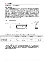
Page 12: ...ance of oscillating forces with minimum residual oscillation the overall centre of gravity of the working weight has to be located within the area specified in Table 2 Limiting coordinates for the position of the centre of gravity of the working weight Figure 3 Centre of gravity range Table 2 Limiting coordinates for the position of the centre of gravity of the working weight HLF07 M HLF12 M HLF25...

Page 13: ...5 0 16 05 2019 Page 13 Figure 4 Attachment using a side plate O Figure 5 Attachment using a side plate S HINWEIS The useful mass has to correspond to the values specified in chapter 4 2 Balance of weights ...

Page 14: ...operated with the power sup ply specified on the name plate The control device IRG1 S is used for the activation of the linear feeder The MSG801 or MSG802 can also be used Please note that an additional CEE connector plug is re quired for the MSG controllers Order number 11006982 Installation of the plug is only to be carried out by technically qualified personnel accord ing Figure 6 End of the wi...

Page 15: ...n and can be applied to each of the two vibrating sections Table 3 Linear track dimensions HLF07 HLF12 HLF25 HLF50 Length mm 400 500 600 800 Breath mm 17 17 24 24 4 2 Balance of weights The oscillating forces in the base plate of the Afag Linear Feeder are compensated al most completely due to the principle of opposing oscillations push pull This balance of oscillating forces is however only achie...

Page 16: ...near Feeder is a spring weight based vibrating system that operates by mak ing use of resonance Weights that are not exactly balanced require a spring stiffness modification Movable adjustment plates are provided at the base plate attachment of the spring assemblies see Figure 7 The natural frequency can be adjusted by moving these adjustment plates Figure 7 Spring assembly with adjustment plates ...

Page 17: ...o be pushed downwards or if the weight difference is significant a leaf spring may have to be removed The test has to be repeated afterwards If the feed rate decreases immediately on loosening the screws the Linear Feeder ad justment is too soft The adjustment plates then have to be pushed upwards or if neces sary an additional leaf spring has to be fitted The test has to be repeated afterwards Wh...

Page 18: ...ure attachment The values specified in Table 5 are only applicable for the respective power supply When making adjustments it is imperative that the surfaces of the magnet core and ar mature are exactly parallel to each other To achieve the required precision it is neces sary to tighten the screws alternately and in stages Table 5 Settings for the air gap between armature and magnet core Type Powe...

Page 19: ...ds and head supports according to DIN 912 or DIN 931 Tightening torques MSp in Nm Screw Strength class 8 8 Strength class 10 9 Strength class 12 9 M4 2 8 4 1 4 8 M5 5 5 8 1 9 5 M6 9 5 14 0 16 5 M7 15 5 23 0 27 0 M8 23 0 34 0 40 0 M10 46 0 68 0 79 0 M12 79 0 117 0 135 0 M14 125 0 185 0 215 0 M16 195 0 280 0 330 0 M18 280 0 390 0 460 0 M20 390 0 560 0 650 0 M22 530 0 750 0 880 0 M24 670 0 960 0 1120...

Page 20: ...if they are heavily worn to replace them entirely Here the vibration parts must be supported in vertical direction Then only one spring package at a time may be removed because otherwise the vibration parts would move making it impossible to guarantee that they function properly CAUTION The leaf springs must not be oiled or greased as this would make the springs sticky and in turn adversely affect...

Page 21: ...h oscillation amplitude Check air gap The drive is improperly adjusted i e the system s natural frequency does not match the exciting frequency Adjust the drive by changing the spring stiffness Change the position of the adjustment plates Tighten the screws of the spring assemblies CAUTION Ad just the conveyors according to the operating manual The weight moment of inertia of the conveyor bowl exc...

Page 22: ...tude Check air gap The drive is improperly adjusted i e the system s natural frequency does not match the exciting frequency Adjust the drive by changing the spring stiffness Change the position of the adjustment plates Tighten the screws of the spring assemblies CAUTION Ad just the conveyors according to the operating manual The weight moment of inertia of the conveyor bowl exceeds the maximum pe...

Page 23: ...eaf spring 50203471 HLF25 Leaf spring 50254134 HLF50 Leaf spring 50411551 Table 7 Spare parts Type Designation Power supply Order number HLF07 Magnet 230V 50Hz 15054450 115V 60Hz 15002283 HLF12 Magnet 230V 50Hz 50277472 115V 60Hz 50277904 HLF25 Magnet 230V 50Hz 50270048 115V 60Hz 50280087 HLF50 Magnet 230V 50Hz 15019167 115V 60Hz 50307820 ...

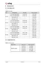
Page 24: ...ht GM12 mass 25g 50216708 Side plate O 12 50197284 Side plate S 15 50216714 HLF25 Trimming weight NM25 mass 100g 50217316 Trimming weight GM25 mass 50g 50217312 Side plate O 25 50197285 Side plate S 25 50217314 HLF50 Trimming weight NM50 mass 100g 50217677 Trimming weight GM50 mass 50g 50217621 Side plate O 50 50197286 Side plate S 50 50217676 6 2 Adjustment aids Table 9 Distance gauge Designation...

Page 25: ...peeds are infinitely adjustable due to magnet current and thus magnetic force variability Soft starting all IRG and MSG types can be mounted in various different ways and offer extra controls for photoelectric barriers initiator elements or extern 24VDC signal For a detailed description of the controllers refer full range catalogue from AFAG GmbH Third party controllers can also be used as long as...

Page 26: ... Sales sales afag com www afag com Switzerland Afag Automation AG Zuführtechnik Fiechtenstrasse 32 CH 4950 Huttwil Tel 41 0 62 959 86 86 Fax 41 0 62 959 87 87 7 Disposal HLF feeders that are no longer in use should not be disposed of as complete units but dismantled into separate materials and recycled Non recyclable components must be disposed of correctly ...

Reviews: