background image


UG 20-UG 25-OI-vers. 3.5 gb. 20190409


Table of contents 

Table of contents ........................................................................................................ 3


1.0.0 EC Declaration for Incorporation (Document original) ....................................... 5


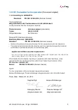
1.1.0 According to: 2006/42/EG .............................................................................. 5


2.0.0 Module Information ............................................................................................ 6


2.1.0 Transport and storage (packing and unpacking) ............................................ 6


2.1.1 Assembly for the gripper ................................................................................ 7


2.1.2 Mounting for the gripper finger ....................................................................... 7


2.1.3 Hole matrix and centering bushings ............................................................... 8


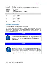
2.1.4 Tightening torques for bolts ............................................................................ 9


3.0.0 Montage Instructions (Document original) ....................................................... 10


3.1.0 Manufacturer address: ................................................................................. 10


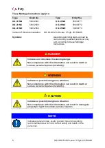
3.1.1 Symbols ....................................................................................................... 11


3.1.2 General description ...................................................................................... 11


3.1.3 General description for the module UG 20 / UG 25 ..................................... 12


3.1.4 Scope of supply ........................................................................................... 13


3.1.5 Guarantee .................................................................................................... 14


3.1.6 Areas of application ...................................................................................... 14


3.1.7 Dimensions drawing UG 20 ......................................................................... 15


3.1.8 Technical data of the UG 20 ........................................................................ 16


3.1.9 Preferred combinations UG 20 ..................................................................... 17


3.2.0 Module stresses UG 20 ................................................................................ 18


3.2.1 Dimensions drawing UG 25 ......................................................................... 20


3.2.2 Technical data of the UG 25 ........................................................................ 21


3.2.3 Preferred combinations UG 25 ..................................................................... 22


3.2.4 Module stresses UG 25 ................................................................................ 23


3.2.5 Pneumatic connection for the UG-Universal gripper .................................... 25


3.2.6 Preparation for Commissioning .................................................................... 26


3.2.7 Fitting the proximity switch in the module grooves ....................................... 27


3.2.8 Example of application of sensor technology combined with specially  formed 
grip fingers (depending on application): ................................................................ 28


Summary of Contents for UG 20 Series

Page 1: ...iversal Gripper UG 20 UG 25 Declaration of Incorporation Module Information Montage Instructions Maintenance Instructions Translation of the Original Montage Instructions copyright by Afag Automation...

Page 2: ...nstructions DANGER Indicates an immediate threatening danger Non compliance with this information can result in death or serious personal injuries invalidity WARNING Indicates a possible dangerous sit...

Page 3: ...l description 11 3 1 3 General description for the module UG 20 UG 25 12 3 1 4 Scope of supply 13 3 1 5 Guarantee 14 3 1 6 Areas of application 14 3 1 7 Dimensions drawing UG 20 15 3 1 8 Technical dat...

Page 4: ...9 4 0 0 Maintenance instructions 29 4 1 0 Maintenance and servicing of the UG 20 25 Universal gripper 29 4 1 1 Servicing 30 4 1 2 Accessories the UG 20 UG 25 31 4 1 3 Trouble shooting 31 4 1 4 Disasse...

Page 5: ...documents shall be sent to a reasoned request by national authorities in printed documents or electronically pdf Applied and fulfilled essential requirements 1 1 1 1 1 1 1 2 1 2 3 1 2 4 4 1 3 1 3 5 1...

Page 6: ...ked in the original cardboard box if the module is not handled properly it may fall out of the box when unpacking and cause injuries to limbs or squeeze your fingers NOTE Technical specification the s...

Page 7: ...or from below Use the centering bushings included in the scope of supply to determine the position 2 1 2 Mounting for the gripper finger NOTE Further elements to be mounted can be attached to the fast...

Page 8: ...al gripper UG 20 UG 25 Hole matrix 20x20mm Hole matrix 30x30mm Thread bore hole M3 Thread bore hole M4 Centering bushings H7 5x2 5mm Centering bushings 7x3mm Use the centering bushings included in the...

Page 9: ...nted loads under the ambient and Installation conditions defined for this module see Technical data The UG Universal gripper can be installed in the horizontal or vertical position NOTE These Montage...

Page 10: ...UG Universal gripper pneumatic Types UG 20 and UG 25 Sequential series No 50xxxxxx This is an incomplete machine Who installs this incomplete machine or assemble with other machines a risk assessment...

Page 11: ...y and health of the personnel 3 1 2 General description The series of the UG 20 25 Universal gripper is used for the linear smooth movement of rigidly mounted loads under the ambient and Installation...

Page 12: ...cted from dirt and dust by the cover plate 11 The grippers are available as type NN without spring preload NC pressureless closed and NO pressureless open They change of design is not possible To quer...

Page 13: ...tage Instructions should be read carefully before carrying out any activity on or with the module The module may only be deployed in accordance with the intended use Modifications on the module that a...

Page 14: ...he other generally accepted safety relevant and occupational safety and health regulations are to be followed The term of the warranty on Afag handling components and systems is 24 months following co...

Page 15: ...UG 20 UG 25 OI vers 3 5 gb 20190409 15 3 1 7 Dimensions drawing UG 20...

Page 16: ...16 UG 20 UG 25 OI vers 3 5 gb 20190409 3 1 8 Technical data of the UG 20...

Page 17: ...UG 20 UG 25 OI vers 3 5 gb 20190409 17 3 1 9 Preferred combinations UG 20...

Page 18: ...18 UG 20 UG 25 OI vers 3 5 gb 20190409 3 2 0 Module stresses UG 20...

Page 19: ...UG 20 UG 25 OI vers 3 5 gb 20190409 19...

Page 20: ...20 UG 20 UG 25 OI vers 3 5 gb 20190409 3 2 1 Dimensions drawing UG 25...

Page 21: ...UG 20 UG 25 OI vers 3 5 gb 20190409 21 3 2 2 Technical data of the UG 25...

Page 22: ...22 UG 20 UG 25 OI vers 3 5 gb 20190409 3 2 3 Preferred combinations UG 25...

Page 23: ...UG 20 UG 25 OI vers 3 5 gb 20190409 23 3 2 4 Module stresses UG 25...

Page 24: ...24 UG 20 UG 25 OI vers 3 5 gb 20190409...

Page 25: ...sal gripper NOTE Minimal compressed air quality according to ISO 8573 1 2010 7 4 4 P1 Close connection P2 Open connection 1 Compressed air connection 4 One way restrictor 2 Maintenance unit 5 Gripper...

Page 26: ...e sensor for proper functioning and readjust if necessary Retighten the fastening screw Reinstall the cover Start up of the UG Universal gripper Aerate the total system slowly Pay attention to the per...

Page 27: ...g Piece in the groove 2 Screw for fastening the proximity Switch in the clamping piece 4 Clamping piece Fitting the proximity switch 1 Insert the proximity switch 1 with clamping piece in the C groove...

Page 28: ...or inductive sensors To guarantee highest precision this position is queried by two inductive sensors These are set in such a way that one sensor responds and the second one does not respond Through...

Page 29: ...d down do not use any aggressive cleaners 1 Montly Check the safety labels for damage readability and cleanliness The shock absorbers and stop screws must undergo regular functionality checks and be r...

Page 30: ...low should be used Festo special oil Avia Avilub RSL 10 BP Energol HPL 10 Esso Spinesso 10 Shell Tellus Oil C 10 Mobil DTE 21 Blaser Blasol 154 Oil quantity 5 10 oil drops per 1000 l air Viscosity ran...

Page 31: ...PNP NO M8x1 11016714 50093507 50313987 4 1 3 Trouble shooting Fault Possible cause Fault clearance Grip jaws do not move to the final position Useful load too high Reduce useful load Pressure too low...

Page 32: ...n be exchanged by the customer itself when the guarantee has expired NOTE All the other faulty parts must exclusively be replaced by company Afag Automation AG When the customer detects that the respe...

Page 33: ...UG griper modules which cannot be used any more must not be disposed off as a complete unit but must be disassembled and recycled according to the type of material Materials than cannot be recycled mu...

Page 34: ...34 UG 20 UG 25 OI vers 3 5 gb 20190409...

Page 35: ...UG 20 UG 25 OI vers 3 5 gb 20190409 35...

Page 36: ...Afag Automation AG Fiechtenstrasse 32 4950 Huttwil Switzerland Tel 41 0 62 959 86 86 Fax 41 0 62 959 87 87 e mail sales afag com Internet www afag com...

Reviews: