UG 20-UG 25-OI-vers. 3.5 gb. 20190409
7
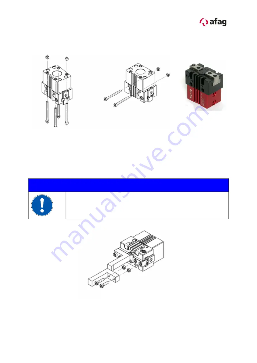
2.1.1 Assembly for the gripper
Depending on the application the gripper can be attached from the side or from
below:
Use the centering bushings included in the scope of supply to determine the position.
2.1.2 Mounting for the gripper finger
NOTE
Further elements to be mounted can be attached to the fastening
threads for the holding-down device.
(see chapter Description)
Installation from below
Installation from the side
Fitting of grip fingers
Summary of Contents for UG 20 Series
Page 15: ...UG 20 UG 25 OI vers 3 5 gb 20190409 15 3 1 7 Dimensions drawing UG 20...
Page 16: ...16 UG 20 UG 25 OI vers 3 5 gb 20190409 3 1 8 Technical data of the UG 20...
Page 17: ...UG 20 UG 25 OI vers 3 5 gb 20190409 17 3 1 9 Preferred combinations UG 20...
Page 18: ...18 UG 20 UG 25 OI vers 3 5 gb 20190409 3 2 0 Module stresses UG 20...
Page 19: ...UG 20 UG 25 OI vers 3 5 gb 20190409 19...
Page 20: ...20 UG 20 UG 25 OI vers 3 5 gb 20190409 3 2 1 Dimensions drawing UG 25...
Page 21: ...UG 20 UG 25 OI vers 3 5 gb 20190409 21 3 2 2 Technical data of the UG 25...
Page 22: ...22 UG 20 UG 25 OI vers 3 5 gb 20190409 3 2 3 Preferred combinations UG 25...
Page 23: ...UG 20 UG 25 OI vers 3 5 gb 20190409 23 3 2 4 Module stresses UG 25...
Page 24: ...24 UG 20 UG 25 OI vers 3 5 gb 20190409...
Page 34: ...34 UG 20 UG 25 OI vers 3 5 gb 20190409...


