background image

11

INSTALLATION INSTRUCTIONS

IDEAA

®

 Interior Distribution Cabinet

© 2016, AFL, all rights reserved. Revision C, 3.3.17

   Specifications are subject to change without notice.

CONNECT DISTRIBUTION FIBER

1.  If not already removed, remove the shipping screws from each side of the swing down tray. A total of two screws 

will be removed. 

(Figure 3)

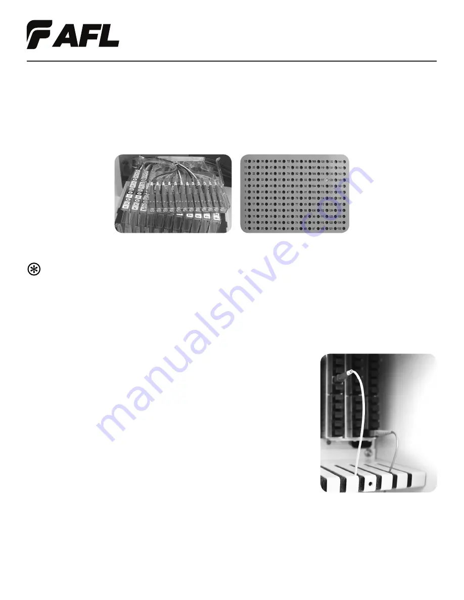
2.  Using local engineering practices, determine the appropriate distribution fiber to be connected. Remove the 

corresponding fiber storage cartridge from the swing down tray by pushing in and pulling up on the cartridge arms. 

(Figure 19)

Note: The cartridges and distribution fibers are numbered to assist in fiber identification. 

Additionally, distribution fibers may be identified by placing a red light on the customer side of the fiber 

and locating the fiber on the swing down tray. (Figure 19)

3.  Remove the desired distribution fiber from the cartridge by sliding the connector out of the housing location 

and continue to route the cable out of the cartridge.

4.  For best practice, it is recommended that the distribution fiber be removed from 

all Velcro and routed back to the cable transition. 

Ensuring the distribution fiber has a clear path to the fiber routing section of the IDC.

5.   Use local accepted practices to clean the distribution fiber connector end face. 
6.  Connect the distribution fiber to the appropriate port on the IDEAA Splitter Module. 

Use the foam fiber relief to route the distribution fiber to the fiber routing section 

of the IDC, employing a similar technique to that used with the input 

jumper cable. 

(Figure 20)

Figure 19

Figure 20

Summary of Contents for IDEAA 144F

Page 1: ...INSTALLATION 4 CABLE PREPARATION 4 CABLE INSTALLATION 5 COMPRESSION FITTING INSTALLATION 5 DISASSEMBLE COMPRESSION FITTING CABLE REPLACEMENT 6 SPLICING 6 DISTRIBUTION CABLE INSTALLATION MPO DISTRIBUTION CABLE 6 DISTRIBUTION CABLE INSTALLATION MPO PIGTAIL SPLICING 8 IDEAA SPLITTER MODULE INSTALLATION MOUNT IDEAA SPLITTER MODULE 9 IDEAA SPLITTER MODULE INSTALLATION ACTIVATE IDEAA SPLITTER MODULE 9 I...

Page 2: ...the IDC utilize the IDEAA splitter module to enable versatility across the platform The IDC utilizes innovative jumper routing to enable efficient fiber management utilizing equal length pigtails for the entire cabinet The IDEAA IDC provides MDU fiber distribution in an extremely compact size Parameter Value Splitter Capacity Up to 5 Modules Input Pass Through Ports 12 Dimensions L x W x H in cm 2...

Page 3: ...e installed lag screws 5 Secure the cabinet to the wall by tightening the three lag screws Before the lag screws are completely tightened a level may be used to ensure that the cabinet is in the desired position REQUIRED TOOLS 216 style Socket Tool Phillips Head Screwdriver 1 Locate the three bracket mounting positions on the back of the 144F IDC Figure 1 2 Using a standard 216 style tool or simil...

Page 4: ...tall the enclosure door over the appropriate hinge pins 3 Review the label and diagram orientation on the IDC door If necessary apply the included Replacement Door Label Kit in the appropriate positioning 4 Using a standard 216 style socket tool or similar lock the cabinet CABLE PREPARATION Caution Fiber optic cable is susceptible to damage from excessive bending pulling or crushing forces At ever...

Page 5: ...ute the unused buffer tubes through the fiber management rings located on the side wall of the IDC Figure 7 CABLE INSTALLATION COMPRESSION FITTING INSTALLATION Caution In order to avoid micro bends or fiber damage do not over tighten the compression fitting around the fiber cable 1 Ensure that the mounting hole is free from burrs and that the cabinet surface is smooth and free of debris 2 Place th...

Page 6: ...n splice tray holder with the hook and loop band 7 The fiber management rings on the side wall of the IDC may be used for slack storage Figure 9 8 Return the swing down splice tray holder to the upright position and secure the shipping screw DISTRIBUTION CABLE INSTALLATION MPO DISTRIBUTION CABLE The top plate of the 144F IDC may be removed to aid in the distribution cable installation process Note...

Page 7: ...ug the connector into the appropriate port Figure 11 9 Use the fiber management rings to route the MPO distribution cable through the back side of the 144F IDC Figure 12 Note A FUSEConnect MPO Splice On Connector may be spliced onto a non connectorized distribution cable The FUSEConnect MPO Splice On Connector application will utilize the same cable installation and routing techniques outlined in ...

Page 8: ...g down splice tray holder in order to begin splicing Do not remove this screw from the swing down tray holder Figure 4 8 Prior to splicing ensure that adequate slack for both the distribution fiber and the MPO pigtail fiber is stored within the splice tray Mark fibers for splicing 9 Clean the fiber per accepted local practice using an approved fiber cleaner 10 Follow accepted local practice for pr...

Page 9: ... Nylatch Plunger ACTIVATE IDEAA SPLITTER MODULE An IDEAA Splitter Module that has been mounted into the IDC is not active until it has been connected to the Input Field Caution When working with fiber optics do not look directly into the end of the fiber cable or adapter port A power meter may be used to determine if the cable or port is dark Or use locally accepted fiber optic safety practices 1 ...

Page 10: ...pposite end of the jumper into the desired port on the input panel Use the foam fiber relief to route the jumper cable to the fiber routing section of the IDC Figure 17 4 Route the remaining jumper slack through the fiber routing section of the IDC Figure 18 5 Use local accepted practices to label the input fiber connection in the appropriate space on the door label as applicable 6 Repeat Steps 1 ...

Page 11: ... may be identified by placing a red light on the customer side of the fiber and locating the fiber on the swing down tray Figure 19 3 Remove the desired distribution fiber from the cartridge by sliding the connector out of the housing location and continue to route the cable out of the cartridge 4 For best practice it is recommended that the distribution fiber be removed from all Velcro and routed...

Page 12: ...C is capable of supporting up to 72 direct connections to the living unit through the use of a MDU drop cable for applications in which the interconnect panel will be bypassed Caution Fiber optic cable is susceptible to damage from excessive bending pulling or crushing forces At every stage of the installation process ensure that the fibers are free from unintentional cuts knick or bends to avoid ...

Page 13: ...ly 12 Using local engineering practices determine which port on the IDEAA Splitter Module will be used for the MDU drop connection 13 Use local accepted practices to clean the distribution fiber connector end face 14 Connect the distribution fiber to the appropriate port on the IDEAA Splitter Module Use the foam fiber relief to route the distribution fiber to the fiber routing section of the IDC e...

Page 14: ...ridge arms 2 Remove the desired distribution fiber from the cartridge by sliding the connector out of the housing location and continue to route the cable out of the cartridge 3 For best practice it is recommended that the distribution fiber be routed back to the cable transition Ensuring the distribution fiber has a clear path to the fiber routing section of the IDC 4 Use local accepted practices...

Reviews: