background image

Summary of Contents for TT-AFM

Page 1: ...iI TT AFM I I if iI Users Guide AFM Wo op Part 10 4172 10 1 UsersGuide Vi S ...

Page 2: ...shop equipment means that it has been designed tested and certified as complying with all applicable European Union CE regulations and recommendations Warnings Cautions Notes The following are definitions of the warnings cautions and notes that may be used in this manual to call attention to important information regarding personal safety safety and preservation of the equipment or important tips ...

Page 3: ...5 Display 3 2 2 6 Tip Retract 3 2 2 7 Control 3 2 3 System Window 3 2 3 1 Z Noise 3 2 3 2 Z High Voltage Gain 3 2 3 3 Xyz Calibration 3 3 Virleo View Software 4 Measuring Images With the TT AFM 4 1 Operating the Video Microscope 4 2 Exchanging Samples 4 3 Exchanging Probes 4 4 Aligning the Light Lever Force Sensor 4 5 Optical Assisted Tip Approach 4 6 Contact Mode Imaging 4 7 Vibrating Mode Imagin...

Page 4: ...r Files B 3 Data Files Appendix C Calibration Appendix D Probes Appendix E Technical Information E 1 Electronic Bock Diagrams E 2 EBox and Modes Pin Assignments E 3 Sample and Probe Holder Mechanical Drawings it Appendix F Optimizing GPID Parameters Page 4 ...

Page 5: ...sensed with the photodetector With this light lever forces as small as a pica newton are possible With such small forces very small probes may be used With micro machining methods probes can have diameters of only a few nanometers The light lever can be made more sensitive by vibrating the cantilever with a small piezoelectric ceramic and modulating the light When the vibrating probe interacts wit...

Page 6: ...tage is a modes connector Signals reqUired for implementing additional modes such as conductive AFM STM and EFM are provided Additional information on the cable configuration is provided in Appendix C 2 3 EBox The EBox sends and receives signals from the computer through a single USB cable Electronic signals are then sent to the stage trough a 60 pin ribbon cable Additionally a grounding cable is ...

Page 7: ...ftware a Plug USB memory stick into the computer I b Copy the contents of the folder AFMWorkshop to the desktop c Once on the desktop open the folder AFMWorkshop and select setup exe d Follow the installation instructions I Gwyddion Image Analysis Software Gwyddion is open source software and the latest version of this image analysis software is available on the I Internet at http gwyddion net Add...

Page 8: ...s are loaded into the software Changing the files used by the program is possible with the File buttons Also these files may be edited to change It parameters with a text editor such as Notepad Appendix XX lists the contents of both the configuration and scanner file It It It t Page S 3 2 AFM View Software Once launched the AFM View software has three screens that can be viewed by pressing the tab...

Page 9: ...or There is a switch for turning the laser On and Off Note After the TT AFM light lever is set up for the first time the thumb screws used for laser alignment do not need to be turned more than a few turns 3 2 1 4 Tune Frequency The Tune Frequency window is used for selecting the optimal conditions for making Vibrating mode images There are several controls in the window They are Amplitude Phase L...

Page 10: ...le range of the piezoelectric scanner is measured with the Range Check option When Started the piezoelectric scanner is moved in a square motion which can be readily observed with the video optical microscope Caution Always visually monitor the position of the Z motor The Z motor can drive the cantilever into the xyz piezoelectric scanner and damage both the probe holder and the scanner 3 2 1 7 Au...

Page 11: ...eters required for scanning are presented in the Scan Setup window Once scanning is started these parameters may not be changed The parameters are The scan can be either 2 D which scans just the X axis or 3 D which scans the X and Yaxis Scan Rate The rate in Hertz that the probe is scanned across the surface in the X direction Scan Lines The number of lines in the Y axis and the number of pixels m...

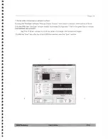
Page 12: ...changing the appearance of 7e ma i_ E the images displayed in the Scan window They are Right Image rz_ERR Left Image The source of the image displayed in the left f image window I Background fLi C g Displa Light Shaded Right Image The source of the image displayed in the right image window Pallet Pall t 1 Background When Line Leveling is selected the background is subtracted from the image one lin...

Page 13: ... ceramic in the xyz scanner can have 14 gains This function allows reducing the Z gain of the high voltage amplifier Reducing the gain reduces the dynamic range of the ceramic but reduces the noise floor of the instrument 3 2 3 3 Xyz Calibration When scanning a standard test pattern the values in this sub window are changed Appendix C explains how to calibrate the TT AFM Note Changing the calibrat...

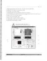
Page 14: ... software package We recommend optimizing the parameters for the particular type of sample you want to visualize Before operating the video camera it must be properly aligned see Appendix A To launch the video view software a From the desktop open folder RZ300C b Click on the RZ300C icon to launch the software Start Image Display English Chinese Capture Image Pause Image Display Image Pixel Densit...

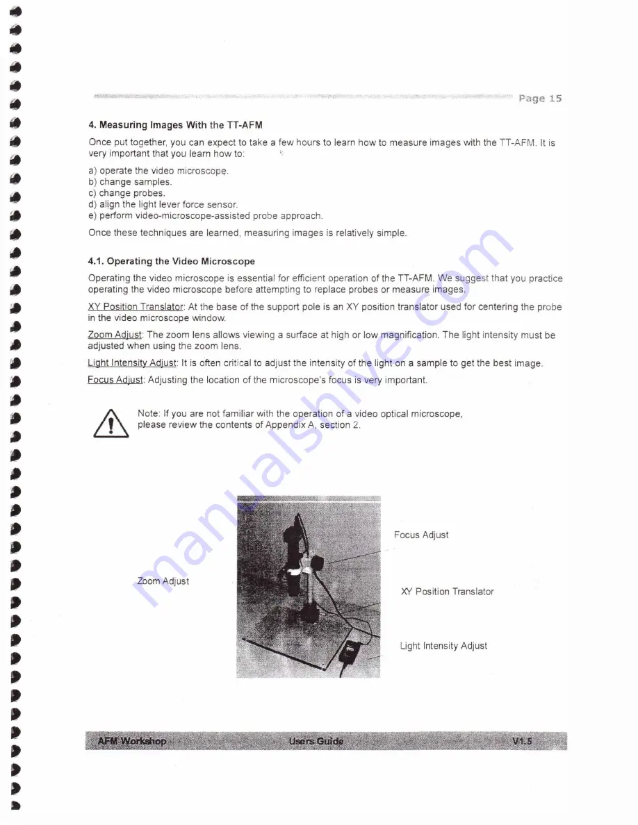
Page 15: ... the video microscope before attempting to replace probes or measure images XY Position Translator At the base of the support pole is an XY position translator used for centering the probe II in the video microscope window Zoom Adjust The zoom lens allows viewing a surface at high or low magnification The light intensity must be adjusted when using the zoom lens Light Intensity Adjust It is often ...

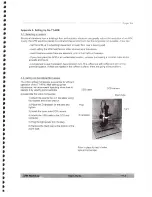
Page 16: ...he image resolution will be substantially degraded II To Exchange Samples a Raise the Z motor all the way up with the Z Motor Control function in the Pre Scan window it It b Remove the probe holder see section 4 3 II II c Place the sample disk on the top of the sample holder Caution Do not place excessive force on the sample holder as it could break away from the piezoelectric ceramic d Slide new ...

Page 17: ...e b Remove the probe holder c Place the probe holder upside down on the probe exchange tool d Put the probe that you want to install on the pedestal of the probe exchange tool e Push down on the probe module such that the spring is moved up and then slide the probe into position To slide the probe into the spring use a sharp pair of tweezers f Place the probe holder back into the microscope t a ...

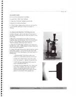
Page 18: ... knobs are turned clockwise tumed clockwise Tips for aligning the laser in the light lever force sensor a After replacing a cantilever the laser and photodetector adjustments are usually less than a single turn b It is often difficult to see the laser spot on the cantilever because the cantilever reflects the light c Bringing the cantilever within a mm of the sample s surface can help because you ...

Page 19: ...nter of their range It II c Turn the detector knob at the top of the sensor counter clockwise to the left until light is visible on the cantilever substrate This should only require one or two turns j d Use the two laser alignment knobs to walk the laser onto the cantilever lit 5 When the laser is on the cantilever in the right position contact a position is different the vibrating position move t...

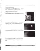
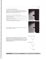
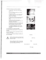
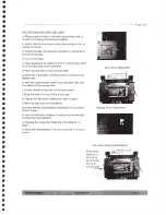
Page 20: ...he it probe down until it is also in focus At the right are two images of a probe as it moves toward a surface Care it must be taken not to hit the surface with the probe it it Note If the tip touches the surface before the feedback is activated the tip may be damaged or even broken lip Away From Surface Typically when doing tip approach with the AFM the laser is on The laser focus spot can be see...

Page 21: ... laser on the probe The laser spot should be about halfway down the cantilever the T 8 signal must be greater than one S Select Contact in the Scan Mode window II Sa Focus video microscope on sample s surface Sb If this is the first scan since opening the AFM Workshop software click on Start in the Range Check window til 6 In the Pre Scan window use the Manual Z Motor Control to move the motor to ...

Page 22: ...Stop function in the Control window 14 Select 3 D scan in the Scan Setup window 15 In the Control window activate Start 16 When the scan is completed the light turns green 17 If desired select a different zoom box and start the scan 18 When finished scanning press Tip Retract Note At the end of every scan data is automatically stored in a pre selected directory p Sm To S I l l tm2llf8 45 0 AO O 35...

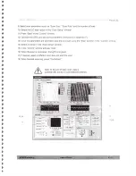
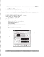
Page 23: ... Appendix D for a probe recommendation 3 Focus the video optical microscope on the AFM probe 4 Follow the instructions in section 4 4 to align the laser on the probe 5 Select Vibrating in the Scan Mode window 5a Initiate the Range Check function 6 Select the frequency 6a Set the lower limit to the number on the probe box 6b Set the higher limit to the number on the probe box 6c Set the number of p...

Page 24: ...mple probe just out of focus 9 In the AFM View Pre Scan window initia e Automated Tip Approach Wait for the green light to indicate I that feedback was achieved 9a If the Z Drive indicator is not at the center of its range start tip approach again 10 With the Scan tab at the top of the AFM View window open the Scan window 10 8 9 a ...

Page 25: ...p the 2 D scan using the Stop function in the Control window 16 Select 3 D scan in the Scan Setup window 17 In the Control window activate Start 18 When the scan is completed the light turns green 19 If desired select a different zoom box and start the scan 20 When finished scanning press Tip Retract Note At the end of every scan data is automatically stored in a pre selected directory P J T p S i...

Page 26: ...o see if a location has a problem is to fill a coffee cup with coffee and set It in the potential location If there are ripples in the coffee s surface there are going to be problems A 2 Setting Up the Optical Microscope The video optical microscope is essential for efficient operation of the TT AFM After setting up the microscope we recommend spending some time to CCO camera USB cable operate it ...

Page 27: ...image on the computer screen use the focus adjust on the video microscope to sharpen the image 7 Increase the magnification with the zoom tube adjuster and increase the light intensity as needed A 3 Connecting the TT AFM to the Cables a Connect the USB cable between the computer and the EBox b Connect the 60 pin ribbon cable between the EBox and the TT AFM stage c Connect the grounding wire betwee...

Page 28: ...install a xyz piezo scanner c Place the TT AFM stage under the zoom tube such that the hole in the LL force sensor is directly below the zoom tube optical objective d Adjust the height of the zoom tube so that the bottom of the tube is about 115 mm from the top of the AFM sample holder Move that stage by hand and adjust the optical focus 1 Place a probe in the probe holder see section 4 3 and plac...

Page 29: ...th the upper thumb screw move the laser light until it is visible on the sample disk i Loosen the set screw that is holding the laser j Slide the laser in or out until it is focused k Tighten the set screw holding the laser in place I Move the light out to the cantilever m Place the two photodetector translators is the center of their range n Use asm lll piece of paper to make sure that the light ...

Page 30: ... AFM x v tran lator and locate the ribbon cable that plug into the scanner c Plug in the ribbon cable d Screw in the three socket screws that hold the scanner onto the xv translator Caution Do not twist the ribbon cable Doing so will damage the TT AFM electronics at I I It I I Page 30 Connector on back of scanner Hold down screws 3 ...

Page 31: ... the parameter file AFM workshop Atomic Force Microscope configuration File April 27 2010 debugJl ag debug_flag 0 scan Mode scan Mode 0 Motor Drive 50 Acceleration microsteps secA2 velocity microsteps sec 582 Tune Frequency Amplitude v 0 408163 Phase deg 121 224490 Lower Freq Hz 176927 884615 upper Freq HZ 178496 394231 selected Freq Hz 177587 500000 Num steps 100 000000 z Piezo ontrol T n n n rh ...

Page 32: ...File w April 27 2010 system Information serial_No A OOl t Range check t Max X 1960968193 000000 Max Y 1973551105 000000 Min X 1456078849 000000 t Min Y 1003094017 000000 t Margin 3 000000 t ca1 si ze um cal size um 50 000000 calibration x cal 1 v_cal 1 z_cal 11 B 3 Data Files TT AFM data files are stored in a text format At the top of the data file are the parameter used for the scan The format fo...

Page 33: ... X Y and Z b To calibrate in the X and Y axis 1 Measure the actual distance across the image by physically measuring the distance 2 Adjust the parameters for calibration in the System window and rescan the standard sample c To calibrate in the Z direction 1 From the data file measure the number of volts required to scan over a feature 2 Divide the distance by the number of volts to get a calibrati...

Page 34: ...h Width Thickness Force Constant 150 350 Khz 125 225 micron 30 40 micron 0 5 1 micron 30 50 NfM Non Vibrating Mode NVM Probes Non vibrating mode probes can be in the shape of a V or rectanguiar Typical NVM probe specifications are Resonance Frequency 150 350 Khz Length 225 450 micron Width 30 40 micron II Thickness 0 1 0 5 micron I Force Constant 0 1 0 5 N M Each of these probes may have a coaling...

Page 35: ...ix has technical information that may be useful for creating customer instrumentation with the TT AFM Additional information is available in the TT AFM technical guide E 1 Electronic Bock Diagrams I 1 i _ t 9 j _ _ r0 4f t l l V A Ie j l i 7 t ti m f r k D ...

Page 36: ...36 E 2 EBox and Modes Pin Assignments 13 6 Z PH E E le 13 5 t B 7 E 5t R 7 E 5 1 3 iT 5 f ii l d 0815 0 11 1e 13 4 _Z_D UVE le 4 Z_EF R iC7 D 13 3rtICT L t 6 SL i 6 2 JJ F f r c 13 A x T 1 7 13 At 1 DC e 318 ...

Page 37: ... Page 37 E 3 Sample and Probe Holder Mechanical Drawings M _ t l f 1 1 j 8 _ w l j c _ 1 1 Y I _ 1 1 0 1 Jv tU i 1 J ...

Page 38: ...optimal conditions requires practice and some intuition When first learning to operate an AFM it is helpful to operate with a test sample and adjust the PIO settings to see the effect on the Z voltage and the Z error signal as shown in figure below Settings Feedback off Feedback gains too low Feedback gains too high Feedback perfect It It It It It It t Effect Probe bends with the topography Probe ...

Reviews: