background image

Installation and Operation Manual

On-Grid PV Inverter

Version: 03.610100036013/V0.05

Summary of Contents for BNT036KTL

Page 1: ...Installation and Operation Manual On Grid PV Inverter Version 03 610100036013 V0 05 ...

Page 2: ...stallation On grid PV Inverter 3 5 Electrical Connection 3 5 1 PV Connection 3 5 2 Grid Connection 3 5 3 Earth Connection 3 5 4 Communication Connection WIFI Ethernet GPRS RS485 4 Operation 4 1 Control Panel 4 2 Menu Structure 4 3 Startup Setting 5 Commissioning 6 Shut Down Restart the Inverter 6 1 Shut Down Procedures 6 2 Restart the inverter 7 Maintenance Trouble Shooting 7 1 Maintenance 7 2 Fau...

Page 3: ...ualified personnel Three Phase BNT036KTL BNT040KTL Please keep this manual all the time available in case of emergency About This Manual 01 The typical connection diagram for the entire PV system is on grid Circuit Breaker Circuit Breaker 1 Surge Protective Device DCA1 DCA1 PE N L 3 PV Inverter PVA1 AC Grid Circuit Breaker 2 Surge Protective Device Surge Protective Device DCA2 DCA2 PVA2 Circuit Br...

Page 4: ...roof Do not expose the inverter to water rain snow or spray 8 Alternative uses modifications to the inverter not recommended The warranty can become void if the inverter was tampered with or if the installation is not in accordance with the relevant installation instructions Safety Symbols 02 BNT036KTL BNT040KTL 56 61 100 100 Type Max AC Current A Rate current of AC breaker A Circuit Breaker and S...

Page 5: ...C 140 F under high power operation Do not touch the inverter enclosure when operation Residual power discharge Do not open the inverter cover until 5 minutes after disconnection both DC and AC power supply Do not dispose of this device with the normal domestic waste Important notes Read all instructions carefully Failure to follow these instructions warnings and precautions may lead to device malf...

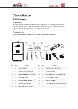
Page 6: ...hown as below Instruction 04 6 7 9 8 11 10 12 13 MC STOP MC 1 2 3 4 5 Certificate of inspection Quick Installation Instructions Warranty card No 1 2 3 4 5 6 7 1 1 1 1 1 1 3 Solar Inverter Certificate Of Inspection Quick Installation Instructions Warranty Card Wall Mounting Bracket Grounding Terminal Plastic Expansion Tube 8 9 10 11 12 13 3 1 1 8 1 1 Mounting Bracket Screw Security Screw Screwdrive...

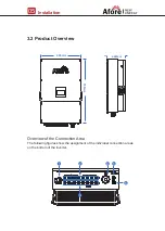
Page 7: ...erview of the Connection Area The following figures show the assignment of the individual connection areas on the bottom of the inverter Installation 05 3 2 Product Overview 465mm 750mm 1 2 5 3 6 4 222mm ...

Page 8: ...r corrosion materials where is suitable for inverter s weight and dimensions The ambient temperature should be within 25 60 between 13 F and 140 F The installation of inverter should be protected under shelter Do not expose the inverter to direct sunlight water rain snow spray lightning etc Installation 06 3 3 Mounting Location No 1 2 3 4 5 6 DC Switch DC Connectors For PV Strings DC Connectors Fo...

Page 9: ...led vertically on the wall or lean back on plane with a limited tilted angle Please refer to below picture Leave the enough space around inverter easy for accessing to the inverter connection points and maintenance 300mm 300mm 500mm 500mm 30 0 Max ...

Page 10: ...Installation 08 3 4 Installation On grid PV Inverter 414mm 22 5mm 22 5mm 44 5mm Step 1 Step 2 Security screw ...

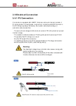
Page 11: ...und must exceed 10 kΩ The polarity from PV strings are correct Use the DC plugs in the accessory The lightning protector should be equipped between PV strings and inverter Disconnect all of the PV DC switch during wiring 3 5 1 PV Connection Warning The fatal high voltage may on the DC side please comply with electric safety when connecting Please make sure the correct polarity of the cable connect...

Page 12: ...tion 10 MC STOP MC MC STOP MC Note You ll hear click sound when the connector assembly is correct Step 3 Note It is strongly recommended to connect by 8 strings of panels for models of 8 sets of DC connectors ...

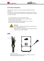
Page 13: ...correctly connected Use the AC plugs in the accessory The surge protector should be equipped between grid and inverter Disconnect the AC grid switch during wiring Installation 11 3 5 2 Grid Connection Warning The fatal high voltage may on the AC side please comply with electric safety when connecting Please make sure the right line of AC grid connected with inverter otherwise inverter could be dam...

Page 14: ...Installation 12 Step 3 Unscrew the row of screws insert the wire harness into the W U V N caps one by one and tighten the screws N Neutral line W V U Live line Step 2 ...

Page 15: ...ctive earth PE terminal to prevent electric shock And make sure this PE terminal is properly grounded Installation 13 3 5 3 Earth Connection Step 1 Step 2 3 5 mm Grounding Terminal Note copper cable or aluminum cable more than 16mm ...

Page 16: ...nsmit the data to the cloud server and display the data on the PC tablet and smart phone Wi Fi GPRS RS485 communication is applicable to the inverter Please refer to Communication Configuration Instruction for detailed instruction Install the Wi Fi GPRS RS485 Communication Step 1 Fasten ...

Page 17: ...lectricity the inverter will active export power limit function based on the monitoring data Please refer to Zero injection Smart Meter Instruction for detailed instruction Step 2 13 14 16 17 19 21 24 25 1 4 7 10 13 14 16 17 19 21 24 25 1 2 3 8 PIN Assignment RS485 A PIN 24 RS485B PIN 25 Zero Injection Port pin assignment 12345678 RJ45 Plug ...

Page 18: ... Indicator FAULT LED Indicator DOWN Touch Button ESC Touch Button UP Touch Button ENT Touch Button RUN LED Indicator Grid Load Distribu on Cabinet L1 L1 L2 L3 L2 L3 PV Array RS485 WiFi Ethernet GPRS Afore Smart Meter PV Array PV Array Router Cloud Server Weather Sta on Energy Meter UP DOWN ESC ENT RUN FAULT GRID POWER PV Inverter PV Inverter PV Inverter ...

Page 19: ...xx ISONGb xx Case_Temp xx C Info Modletemp xx C ScreenTemp xx C Bus xxV Bus xxV RunTime xxxHr SumTime xxxHr Ia xx Ib xx Ic xx Fac Hz Vac V Ua xx Ub xx Uc xx Iac A AC Output System Date Time Date xx xx xxxx Time xx xx xx English Polish 中文 Language Country Energyk xxx x Energyk Etotal x x kwh Etotal Reset Clear ErrRecord Clear RunRecord Factory Reset Enter User PassWord Enter User PassWord Enter Use...

Page 20: ... the error list of inverter including date and time Set the protection parameter of inverter Development function unavailable View WIFI SN and IP address WIFI info View the inverter information Voltage current power and so no Error Record SET ON OFF Check the software version of the control board and display board Version System ...

Page 21: ...fo Version System Info Power 40 000KW 15 6 KWh 497000KWh RUNNING 110 50 0 5 8 11 14 1720 23 t P 11 11 2019 11 00 EDay EAll State Enter Enter UP DOWN Lock setting Language Date Time Country EnergyK Etotal Reset Clear ErrRecord Clear RunRecord Factory Reset SET UP DOWN Adjust the time Date XXXX XX XX Time XX XX XX Date Time SET System Running Protection Communication ...

Page 22: ...tions Commissioning Procedures Turn on the AC switch between inverter grid output and the public grid Turn on the DC switch on the inverter Turn on the PV switch of the system 5 Commissioning UP DOWN ESC ENT RUN FAULT GRID POWER FAULT Red LED Green LED Green LED GRID Green LED RUN POWER LED Indication On Off Green GRID Normal grid connection Non grid Sign Color Explanation POWER Green On Off On Of...

Page 23: ...oblem Turn off the DC switch on the inverter Turn off the PV switch of the system Turn off the AC switch between inverter output and the public grid Follow the procedures below when the inverter needs to be restarted Follow the Shut Down Procedures of Article 6 to shut down inverter Follow the Commissioning Procedures of Article 5 to turn on the inverter Shut Down Restart the Inverter 21 7 Mainten...

Page 24: ...control board IntProtectA Internal protection B Relay fault turn off AC then DC circuit breaker restart the inverter IntProtectB Internal protection C Inverter current protection turn off AC then DC circuit breaker restart the inverter check the each phases AC voltage is correct through LCD IntProtectC Internal protection D Boost current protection turn off AC then DC circuit breaker restart the i...

Page 25: ...YES YES YES YES YES YES YES YES YES YES YES YES YES YES 46 750 x 465 x 222 RS485 WiFi Wire Ethernet GPRS op onal Intelligent Fan Cooling 51 1 4000 IP65 Aluminum 25 60 Transformerless 0 100 EN IEC 61000 6 2 EN IEC 61000 6 3 EN61000 3 2 EN61000 3 3 EN61000 3 11 EN61000 3 12 EN IEC 62109 1 2 UL1547 IEC 60068 2 EN50549 1 EN50438 RD 1699 UNE 217001 RD 413 IEC61727 IEC62116 IEC61683 VDE4105 UL1741 VDE01...

Reviews: