– English –
Technical specifications
FloCo-Top-2
27
FloCo-Top-2KM Optimum Si:
Like FloCo-Top-2KM Si, but with long
filter cup and long sintered plastic filter.
3.2
Function
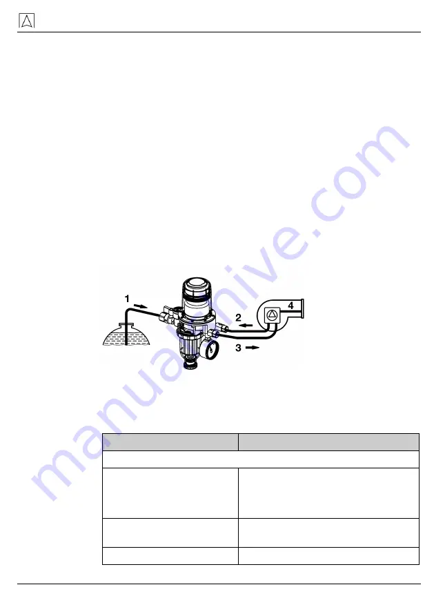
The burner pump draws the fuel oil from the tank via the filter and the
check valve installed in the housing and delivers it to the nozzle. The
excess oil (i.e. the oil exceeding the nozzle capacity) is pumped via
the connection piece of the return line into the float chamber. While
the liquid level gradually increases in the float chamber, the oil is de-
aerated by the de-aeration valve.
When the oil reaches a level of approx. 20-30 mm above the bottom,
the floats begin to operate and actuate the bypass valve, thus deliv-
ering the de-aerated return oil to the suction pipe. This way, the sys-
tem only withdraws the amount of oil from the tank via the filter which
is actually needed for combustion.
The major part of the volume flow to the tank consists of de-aerated
fuel oil and a small portion of fuel oil from the tank which may still
contain air.
1
Q
Tank
= Q
Nozzle
2
Q
Return
3
Q
Flow
4
Q
Nozzle
Fig. 27: Function
4
Technical specifications
Table 4: Technical specifications
Parameter
Value
General specifications
Dimensions (W x H x D)
183 x 308 x 103 mm (type: MM)
183 x 254 x 103 mm (type: KM)
183 x 348 x 103 mm (type: Optimum)
Burner connection
G 3/8 male with 60° cone for burner
hose
Tank connection
G 3/8 female at shut-off valve


