Mounting and commissioning
– English –
FloCo-Top-2
30
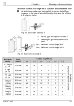
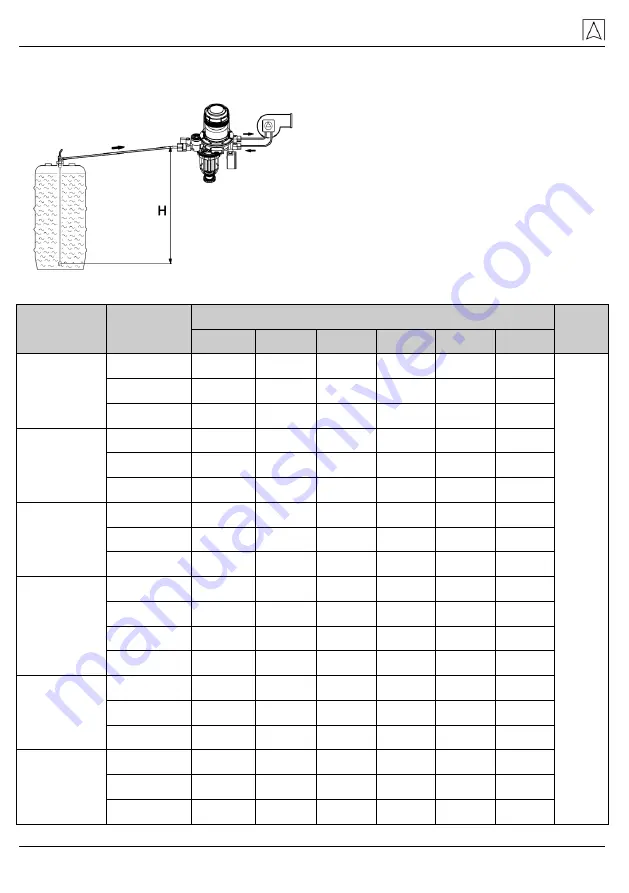
Maximum suction line length with lower tank level
If the suction line is designed as a self-
securing suction line according to the
applicable technical regulations, re-
move all check valves upstream of Flo-
Co-Top-2.
Fig. 29: Application example 1
Nozzle ca-
pacity
Inner
pipe Ø
Suction height H [m]
1.5
2.0
2.5
3.0
3.5
4.0
< 2.5 kg/h
(3 l/h)
Ø 4 mm
32
26
19
13
7
1
Max
im
um po
ss
ible s
uc
tio
n
li
ne length [
m]
Ø 6 mm
>100
>100
>100
68
36
4
Ø 8 mm
>100
>100
>100
>100
>100
14
5 kg/h
(6 l/h)
Ø 4 mm
10
8
6
4
2
1
Ø 6 mm
81
65
49
34
18
2
Ø 8 mm
>100
>100
>100
>100
57
7
7.5 kg/h
(9 l/h)
Ø 4 mm
10
8
6
4
2
0
Ø 6 mm
54
43
33
22
12
1
Ø 8 mm
>100
>100
>100
71
38
4
10 kg/h
(12 l/h)
Ø 4 mm
8
6
4
3
1
0
Ø 6 mm
40
32
25
17
9
1
Ø 8 mm
>100
>100
78
53
28
3
Ø 10 mm
>100
>100
>100
>100
69
8
15 kg/h
(18 l/h)
Ø 6 mm
27
21
16
11
6
0
Ø 8 mm
86
69
52
35
19
2
Ø 10 mm
>100
>100
>100
87
46
5
20 kg/h
(24 l/h)
Ø 6 mm
20
16
12
8
4
0
Ø 8 mm
64
52
39
26
14
1
Ø 10 mm
>100
>100
96
65
35
4


