background image


14

Inbetriebnahme

DE

Heizölfilter 

5.5

Einsatz eines Antiheberventils

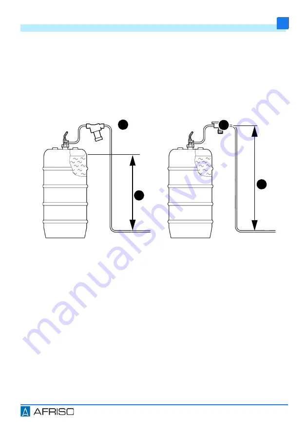
Wenn der maximale Füllstand im Heizöltank höher als der tiefste Punkt der 
Saugleitung liegt, kann bei einer Undichtheit Heizöl durch Saugheberwirkung 
selbsttätig aus dem Heizöltank auslaufen. Als Sicherheitseinrichtung müs-
sen Magnetventile, Membran-Antiheberventile oder Kolben-Antiheberventile 
eingesetzt werden.

6

Inbetriebnahme

1. Öffnen Sie das Absperrventil.


A. Kolben-Antiheberventil KAV

B. Absicherungshöhe mit KAV

C. Membran-Antiheber- oder Mag-

netventil

D. Absicherungshöhe mit Mem-

bran-Antiheberventil

Abbildung 7: Magnetventil, Membran- oder Kolben-Antiheberventil

A

B

C

D

Summary of Contents for 20281

Page 1: ...en Telefon 49 7135 102 0 Service 49 7135 102 211 Telefax 49 7135 102 147 info afriso com www afriso com Copyright 2019 AFRISO EURO INDEX GmbH Alle Rechte vorbehalten MVV TB C 2 15 23 EN 12514 2 Betriebsanleitung Heizölfilter Einstrangfilter V R Zweistrangfilter Z ...

Page 2: ...ung und alle zum Produkt gehörenden Unter lagen an alle Benutzer des Produkts weiter Wenn Sie der Meinung sind dass die Betriebsanleitung Fehler Wider sprüche oder Unklarheiten enthält wenden Sie sich vor Benutzung des Produkts an den Hersteller Diese Betriebsanleitung ist urheberrechtlich geschützt und darf ausschließ lich im rechtlich zulässigen Rahmen verwendet werden Änderungen vorbe halten Fü...

Page 3: ...in unterschiedliche Gefahrenklassen unter teilt 2 2 Bestimmungsgemäße Verwendung Dieses Produkt eignet sich ausschließlich zur kontinuierlichen Filterung fol gender Flüssigkeiten in Ölfeuerungsanlagen Heizöl EL nach DIN 51603 1 Heizöl EL nach DIN 51603 1 und nach DIN SPEC 51603 6 mit 0 20 Fettsäure Methylester FAME nach EN 14214 Dieselkraftstoff nach EN 590 Eine andere Verwendung ist nicht bestimm...

Page 4: ...n und für folgende Zwecke nicht angewendet werden Einsatz mit unverdünnten Additiven Alkoholen und Säuren Einsatz in Druckversorgungsanlagen ohne entsprechende Schutzvorkeh rungen 2 4 Qualifikation des Personals Arbeiten an und mit diesem Produkt dürfen nur von Fachkräften vorgenom men werden die den Inhalt dieser Betriebsanleitung und alle zum Produkt gehörenden Unterlagen kennen und verstehen Di...

Page 5: ...g Das Produkt kann durch unsachgemäßen Transport und Lagerung beschä digt werden HINWEIS UNSACHGEMÄSSE HANDHABUNG Stellen Sie sicher dass während des Transports und der Lagerung des Pro dukts die spezifizierten Umgebungsbedingungen eingehalten werden Benutzen Sie für den Transport die Originalverpackung Lagern Sie das Produkt nur in trockener sauberer Umgebung Stellen Sie sicher dass das Produkt b...

Page 6: ...ng Filtergehäuse mit Anschlüssen G3 8 einem Filtereinsatz einer transparenten Filtertasse einem Absperrven til sowie einem Überströmventil Einstrangfilter Typ Z 500 Z 500 Das Produkt besteht aus einem Messing Filtergehäuse mit Anschlüssen G3 8 Typ Z 500 mit Anschlüssen G einem Filtereinsatz einer transparenten Filtertasse einem Absperrventil sowie einem Überströmventil 4 1 Zulassungsdokumente Besc...

Page 7: ...7 Produktbeschreibung DE Heizölfilter Abbildung 2 Typ R 500 Abbildung 3 Typ Z 500 Z 500 ...

Page 8: ...sing Überwurfmut ter Max 6 bar Kunststoff Filtertasse Nur Saugbetrieb Saugunterdruck Max 0 5 bar Prüfdruck Max 6 bar Einbaulage Senkrecht Filtertasse nach unten V R Z Einstrangfilter Einstrangfilter mit Rücklaufzuführung Zweistrangfilter ohne Kennzeichn Anschluss Tank Brenner G3 8 Anschluss Tank Brenner G 500 Optimum Zulässige Medien siehe Bestimmungsgemäße Verwendung Si Fi St Sinterkunststoffsieb...

Page 9: ...chen Durchfluss Nennleistungen wie die Standard Ausführun gen Typ Stahl 100 µm Filz 50 75 µm Siku 50 70 µm Siku 50 70 µm lang V 500 320 290 250 255 V 500 560 470 390 405 R 500 250 240 210 215 Z 500 220 200 200 205 Z 500 500 400 310 325 Tabelle 1 Öldurchsatz in l h bei p 100 mbar nach EN 12514 2 bei 50 igem Ver schmutzungsgrad des Filtereinsatzes ...

Page 10: ...fdruck Der maximale Rücklaufstrom entspricht dem Fördervolumen der Pumpe da während der Vorbelüftungszeit der gesamte Volumenstrom in den Rücklauf gefördert wird Ein eventueller statischer Vordruck der Ölsäule addiert sich zum maximalen Rücklaufdruck HINWEIS AUSLAUFEN VON ÖL BEI FILTERWECHSEL Stellen Sie sicher dass die Druckversorgungsanlage spannungsfrei geschaltet ist Lassen Sie eventuell vorha...

Page 11: ...eines unisolierten Kesselteils oberhalb zu öffnender Klappen an Feuerungs stellen oder am Rauchkanal montiert wird Stellen Sie sicher dass das Schwimmergehäuse senkrecht nach oben zeigt 1 Montieren Sie das Pro dukt mit Hilfe des beige fügten Halters und drei Bohrblechschrauben 2 Verwenden Sie den Halter als Schablone um die Bohrblechschrauben ein zuschrauben HINWEIS UNDICHTHEIT DES PRODUKTS Stelle...

Page 12: ...esser der Saugleitung darf 4 mm nicht unterschreiten auch wenn die Berechnung der Fließgeschwindigkeit einen kleineren Innendurch messer ergibt Durch die Kapillarwirkung können Luftblasen mit angesaugt werden Luftblasen können eine Störung am Brenner zur Folge haben Eine richtig dimensionierte Saugleitung vermeidet Luftansammlungen in höher gelegenen Leitungsbereichen und Gefällstrecken 1 Bestimme...

Page 13: ...n ungefähr 0 23 m s wird eine Leitung mit Innendurchmes ser 6 mm Rohraußendurchmesser 8 x 1 mm benötigt A Düsenverbrauch l h B Innendurchmesser der Saugleitung mm C Fließgeschwindigkeit des Heizöls m s D Innendurchmesser 4 mm nicht zulässig E Empfohlener Bereich nach DIN 4755 2 Abbildung 6 Nomogramm A B C E D Ø Di ...

Page 14: ...elbsttätig aus dem Heizöltank auslaufen Als Sicherheitseinrichtung müs sen Magnetventile Membran Antiheberventile oder Kolben Antiheberventile eingesetzt werden 6 Inbetriebnahme 1 Öffnen Sie das Absperrventil A Kolben Antiheberventil KAV B Absicherungshöhe mit KAV C Membran Antiheber oder Mag netventil D Absicherungshöhe mit Mem bran Antiheberventil Abbildung 7 Magnetventil Membran oder Kolben Ant...

Page 15: ...en die von der Tankleitung in den Heizölfilter gelangen Die Menge der Luftansammlung ist dabei abhängig von der Fließgeschwindigkeit der Saughöhe oder dem vorhandenem Vakuum Geringe Luftansammlungen in der Filtertasse beeinflussen nicht die Funktion des Produkts Wenn es aufgrund größerer Luftansammlung zu Betriebsstörungen kommt weil aus dem Heizölfilter Luft in die Brenner Leitung gelangt ist die...

Page 16: ...ichtbeachtung dieser Anweisungen kann zu Sachschäden führen Zeitpunkt Tätigkeit Bei Bedarf Reinigen Sie die Kunststoffteile mit einer wässri gen Seifenlauge Jährlich oder bei Bedarf Ersetzen Sie den Filtereinsatz Alle 5 Jahre Ersetzen Sie die Brennerschläuche Spätestens nach 20 Jahren Ersetzen Sie das Produkt Nach Hochwasser Ersetzen Sie den Einstrangfilter mit Rücklaufzu führung R 500 Si R 500 St...

Page 17: ...17 Wartung DE Heizölfilter 8 2 Filtereinsatz tauschen 8 2 1 Filtereinsatz ausbauen B C ...

Page 18: ...18 Wartung DE Heizölfilter ...

Page 19: ...19 Wartung DE Heizölfilter 8 2 2 Filtereinsatz einbauen ...

Page 20: ...tungsdurch messer der Sauglei tung Beim Öffnen des Anti heberventils nach der Vorbelüftungszeit des Brenners kann eine grö ßere Luftblase durch schlagen die eine Stör abschaltung verursachen kann A Legen Sie die Saugleitung korrekt aus siehe Kapitel Sauglei tung dimensionieren B Hohe Strömungsge schwindigkeiten und Saugdruck können in der Filtertasse zu hohen Luftansammlungen füh ren die eine Stör...

Page 21: ...auglei tung Dichten Sie die zylindri sche Rohrverschrau bungen mit Kup fer Flachdichtungen luftdicht im Gehäuse ein Verwenden Sie bei wei chem mittelhartem Kup ferrohr zusätzlich eine Stützhülse Prüfen Sie sämtliche Dichtflächen auf Beschädigungen Schließen Sie das Absperrventil an der Entnahmearmatur und führen Sie eine Vaku umprüfung mindestens 0 6 bar am Vorlaufan schluss des Ölentlüfters durch...

Page 22: ...iften 1 Demontieren Sie das Produkt siehe Kapitel Montage in umgekehrter Reihenfolge 2 Entsorgen Sie das Produkt 11 Rücksendung Vor einer Rücksendung Ihres Produkts müssen Sie sich mit uns in Verbin dung setzen 12 Gewährleistung Informationen zur Gewährleistung finden Sie in unseren Allgemeinen Geschäftsbedingungen im Internet unter www afriso com oder in Ihrem Kauf vertrag ...

Page 23: ... Ersatz und Zubehörteile des Herstellers Nichtbeachtung dieser Anweisung kann zu Sachschäden führen Artikelbezeichnung Art Nr Abbildung Einstrangfilter V 500 Si V 500 St 20292 20294 Zweistrangfilter Z 500 Si Z 500 St Z 500 Fi 20429 20425 20428 Einstrangfilter R 500 Si Rücklauf R 500 St Rücklauf R 500 Fi Rücklauf 20281 20283 20282 ...

Page 24: ...Saugbetrieb 20254 Filtertasse lang Typ Optimum Kunststoff für Saugbetrieb 20258 Filtertasse Typ 500 Messing für Druckbetrieb 20261 Überwurfmutter M64 x 1 5 Messing 10 11 050008 Filtertasse Typ 500 Kunststoff mit Ablassfunktion 20257 Filtertasse Typ Optimum Kunststoff für Saugbetrieb 20262 O Ring für Filtertasse 20422 Rohrverschraubung nach DIN 3852 mit Kupfer Flachdichtung Rohr Ø 8 mm Rohr Ø 10 mm...

Page 25: ...lephone 49 7135 102 0 Service 49 7135 102 211 Telefax 49 7135 102 147 info afriso com www afriso com Copyright 2019 AFRISO EURO INDEX GmbH All rights reserved MVV TB C 2 15 23 EN 12514 2 Operating instructions Fuel oil filters Single line filters V R Dual line filter Z ...

Page 26: ...as all other product related doc uments on to all owners of the product If you feel that these operating instructions contain errors inconsisten cies ambiguities or other issues contact the manufacturer prior to using the product These operating instructions are protected by copyright and may only be used as provided for by the corresponding copyright legislation We reserve the right to modificati...

Page 27: ...lassified according to different hazard categories 2 2 Intended use This product may exclusively be used for continuous filtration of the following liquids in oil fired systems Fuel oil EL as per DIN 51603 1 Fuel oil EL as per DIN 51603 1 and as per DIN SPEC 51603 6 with 0 20 fatty acid methyl ester FAME as per EN 14214 Diesel fuel as per EN 590 Any use other than the application explicitly permit...

Page 28: ...wing purposes Use with undiluted additives alcohols and acids Use in pressure supply systems without appropriate protection precau tions 2 4 Qualification of personnel Only appropriately trained persons who are familiar with and understand the contents of these operating instructions and all other pertinent product docu mentation are authorized to work on and with this product These persons must h...

Page 29: ...Transport and storage The product may be damaged as a result of improper transport or storage NOTICE INCORRECT HANDLING Verify compliance with the specified ambient conditions during transport or storage of the product Use the original packaging when transporting the product Store the product in a clean and dry environment Verify that the product is protected against shocks and impact during trans...

Page 30: ...product consists of a brass filter housing with connections G3 8 a filter insert a transparent filter cup a shutoff valve and a bypass valve Single line filter type type Z 500 Z 500 The product consists of a brass filter housing with connections G3 8 type Z 500 with connections G a filter insert a transparent filter a shut off valve and a bypass valve 4 1 Approvals conformities certifications The ...

Page 31: ...7 Product description EN Fuel oil filters Fig 2 Type R 500 Fig 3 Type Z 500 Z 500 ...

Page 32: ...ss union nut Max 6 bar Plastic filter cup Suction mode only Suction vacuum Max 0 5 bar Test pressure Max 6 bar Mounting position Vertical with filter cup down V R Z single line filter single line filter with return line supply dual line filter No designation Connection tank burner G3 8 Connection tank burner G 500 Optimum Approved media see Intended use Si Fi St Sintered plastic sieve 50 70 μm Fel...

Page 33: ...l flow rates as the standard versions Type Steel 100 µm Felt 50 75 µm Sintered plastic 50 70 µm Sintered plastic 50 70 µm long V 500 320 290 250 255 V 500 560 470 390 405 R 500 250 240 210 215 Z 500 220 200 200 205 Z 500 500 400 310 325 Table 1 Oil flow rate in l h with p 100 mbar as per EN 12514 2 at pollution degree of 50 of filter insert ...

Page 34: ...tion time Any static inlet pressure of the oil column is added to the maximum return pres sure If the pressure resistance is not sufficient at the return side of the burner pump it is recommended to use the automatic fuel oil de aerator Flow Con trol or the filter de aerator FloCo Top NOTICE ESCAPING OIL DURING FILTER REPLACEMENT Verify that the pressure supply system is disconnected from mains Di...

Page 35: ...ampers at furnaces or to the flue gas pipe Verify that the float housing points vertically to the top 1 Mount the product using the enclosed bracket and three self tapping screws 2 Use the bracket as a tem plate when screwing in the self tapping screws NOTICE LEAKING PRODUCT Verify that you use a screwed pipe connection as per DIN 3852 with cylindri cal thread G thread and seal the screwed pipe co...

Page 36: ... the suction line must not be less than 4 mm even if the calculation of the flow rate results in a smaller inside diameter The capillary effect may cause air bubbles to be sucked in Air bubbles can cause a mal function of the burner A properly rated suction line helps to keep air from accumulating in higher pipe sections and sections with downward gradients 1 Determine the diameter of the suction ...

Page 37: ...8 x 1 mm is required for a volume of 20 l h and an average flow rate of approximately 0 23 m s A Nozzle consumption l h B Inside diameter of the suc tion line mm C Flow rate of the fuel oil m s D Inside diameter 4 mm not permissible E Recommended range as per DIN 4755 2 Fig 6 Nomograph A B C E D Ø Di ...

Page 38: ... a leak Solenoid valves diaphragm type anti siphon valves or piston type anti siphon valves must be used to protect against this 6 Commissioning 1 Open the shut off valve A Piston type anti siphon valve KAV B Safe height with KAV C Diaphragm type anti siphon valve or solenoid valve D Safe height with diaphragm type anti siphon valve Fig 7 Solenoid valve diaphragm type anti siphon valve or piston t...

Page 39: ...his is caused by small air bubbles getting from the tank line to the fuel oil filter The air volume is independent of the flow rate the suction height or the existing vacuum Small accumulations of air in the filter cup do not influence the operation of the product If the major accumulations of air result in malfunctions because air from the fuel oil filter gets into the burner line it is advisable...

Page 40: ...leaning the plastic parts Failure to follow these instructions can result in equipment damage When Activity If required Clean the plastic parts with soap suds Annually or if required Replace the filter insert Every 5 years Replace the burner hoses No later than after 20 years Replace the product After a flood Replace the single line filter with return supply R 500 Si R 500 St R 500 Fi ...

Page 41: ...17 Maintenance EN Fuel oil filters 8 2 Replacing the filter insert 8 2 1 Dismounting the filter insert B C ...

Page 42: ...18 Maintenance EN Fuel oil filters ...

Page 43: ...19 Maintenance EN Fuel oil filters 8 2 2 Mounting the filter insert ...

Page 44: ...n the suction line because pipe cross section is too great When the anti siphon valve opens after the pre aeration time of the burner a greater air bubble may pass through which causes the burner to switch off A Properly rate the suc tion line see chapter Rating the suction line B High flow rates and suction pressure can lead to major air accu mulations in the filter cup which may cause the burner...

Page 45: ...r cush ion in the suction line Use cylindrical screwed pipe connections at the housing and seal them with flat copper gaskets air tight Use a stiffener in the case of soft or semi soft copper pipes Check all sealing sur faces for damage Close the shut off valve at the withdrawal fitting and perform a vacuum test at least 0 6 bar at the flow connection of the oil vent Burner pump does not generate ...

Page 46: ...ble directives standards and safety regulations 1 Dismount the product see chapter Mounting reverse sequence of steps 2 Dispose of the product 11 Returning the device Get in touch with us before returning your product 12 Warranty See our terms and conditions at www afriso com or your purchase contract for information on warranty ...

Page 47: ...nd accessories provided by the manufac turer Failure to follow these instructions can result in equipment damage Product designation Part no Figure Single line filters V 500 Si V 500 St 20292 20294 Dual line filter Z 500 Si Z 500 St Z 500 Fi 20429 20425 20428 Single line filters R 500 Si return R 500 St return R 500 Fi return 20281 20283 20282 ...

Page 48: ...Plastic for suction mode 20254 Filter cup long type Optimum Plastic for suction mode 20258 Filter cup brass type 500 Brass for pressure mode 20261 Union nut M 64 x 1 5 brass 10 11 050008 Filter cup type 500 Plastic with drain function 20257 Filter cup type Optimum Plastic for suction mode 20262 O ring for filter cup 20422 Screwed pipe connection as per DIN 3852 with flat copper gasket Pipe Ø 8 mm ...

Page 49: ...en Téléphone 49 7135 102 0 Service 49 7135 102 211 Téléfax 49 7135 102 147 info afriso com www afriso com Copyright 2019 AFRISO EURO INDEX GmbH Tous droits réservés MVV TB C 2 15 23 EN 12514 2 Notice technique Filtre fuel Filtre monotube V R Filtre à deux tubes Z ...

Page 50: ...te la documentation relative au pro duit à tous les utilisateurs du produit Si vous êtes d avis que la notice technique contient des erreurs des contradictions ou des ambiguïtés adressez vous au fabricant avant d uti liser le produit Cette notice technique est protégée au titre de la propriété intellectuelle elle doit être utilisée exclusivement dans le cadre autorisé par la loi Sous réserve de mo...

Page 51: ... la gravité du risque les consignes de sécurité sont réparties dans diffé rentes classes de risques 2 2 Usage normal Le produit est destiné exclusivement au filtrage en continu des liquides sui vants dans les chaudières à fuel Fuel EL selon DIN 51603 1 Fuel domestique EL selon DIN 51603 1 et selon DIN SPEC 51603 6 contenant 0 20 d ester méthylique d acide gras EMAG selon EN 14214 Gazole selon EN 5...

Page 52: ...on dilués alcools et acides Utilisation dans les systèmes d alimentation de pression sans précautions de protection correspondantes 2 4 Qualification du personnel Seul le personnel dûment qualifié est autorisé à travailler sur le produit et avec celui ci après qu il aura connu et compris le contenu de cette notice technique ainsi que toute la documentation faisant partie du produit S appuyant sur ...

Page 53: ...stockage Un transport et un stockage inadéquats risquent de causer des dommages au produit AVIS MANUTENTION INAPPROPRIÉE Assurez vous que les conditions ambiantes spécifiées sont respectées pen dant le transport et le stockage Utilisez l emballage d origine pour le transport Stockez le produit dans un lieu sec et propre Assurez vous que le produit est à l abri des chocs pendant le transport et le ...

Page 54: ... un boîtier filtre en laiton avec raccords G3 8 d un élément filtrant d un bol de filtre transparent d une vanne d arrêt et d un réducteur pression Filtre monotube type Z 500 Z 500 Le produit est composé d un boîtier filtre en laiton avec raccords G3 8 type Z 500 avec raccords G d un élément filtrant d un bol de filtre transpa rent d une vanne d arrêt et d un réducteur pression 4 1 Agréments certi...

Page 55: ...7 Description du produit FR Filtre fuel Figure 2 Type R 500 Figure 3 Type Z 500 Z 500 ...

Page 56: ... raccord en laiton 6 bar max Bol de filtre en matière plastique mode aspira tion uniquement Dépression d aspiration Max 0 5 bar Pression d essai Max 6 bar Position de montage Vertical bol de filtre vers le bas V R Z Filtre monotube Filtre monotube avec retour Filtre à deux tubes Sans désign Raccordement réservoir brû leur G3 8 500 Optimum Liquides approuvés voir Usage normal Si Fi St Tamis en mati...

Page 57: ...ts nominaux que les filtres fuel standards Type Acier 100 µm Feutre 50 75 µm Siku 50 70 µm Siku 50 70 µm long V 500 320 290 250 255 V 500 560 470 390 405 R 500 250 240 210 215 Z 500 220 200 200 205 Z 500 500 400 310 325 Tableau 1 Débit fuel en l h avec p 100 mbar selon EN 12514 2 dégrée d encras sement de l élément filtrant de 50 ...

Page 58: ...ée statique de la colonne d huile sʼadditionne pour donner la pression de retour maximale Si la résistance à la pression n est pas suffisante sur le côté retour de la pompe du brûleur il est recommandé d utiliser les purgeurs d air automa tiques Flow Control ou purgeurs d air automatiques avec filtre FloCo Top AVIS ÉCOULEMENT DU FUEL PENDANT EL CHANGEMENT DU FILTRE Assurez vous que le système de p...

Page 59: ...ir aux endroits de combustion ou au tuyau de tirage Vérifiez que la chambre du flotteur est en position verticale et dirigé vers le haut 1 Fixez le produit à l aide du support fourni et les quatre vis à tôle 2 Utilisez le support comme gabarit pour visser les vis à tôle AVIS INÉTANCHÉITÉ DU PRODUIT Utilisez un raccord tube selon DIN 3852 avec filetage cylindrique filetage G et assurez l étanchéité...

Page 60: ...être inférieur à 4 mm même si le calcul du débit donne un diamètre intérieur plus petit L effet capillaire peut provoquer l aspiration de bulles d air Les bulles d air peuvent entraîner un dysfonctionnement du brûleur Une conduite d aspiration correctement dimensionnée permet d éviter lʼaccu mulation de bulles d air dans les sections hauts et les sections inclinées 1 Déterminez le diamètre de la c...

Page 61: ...aut installer une conduite de diamètre interne de 6 mm diamètre externe de 8 x 1 mm A Consommation du gicleur l h B Diamètre intérieur de la conduite d aspiration mm C Vitesse d écoulement du fuel m s D Diamètre intérieur 4 mm inadmissible E Plage recommandée selon DIN 4755 2 Figure 6 Nomogramme A B C E D Ø Di ...

Page 62: ...voir Des électrovannes des valves anti siphon à membrane ou des valves anti siphon à piston doivent être uti lisés comme dispositifs de sécurité pour éviter cela 6 Mise en service 1 Ouvrez la vanne d arrêt A Valve anti siphon à piston KAV B Hauteur de protection avec KAV C Valve anti siphon à membrane ou électrovanne D Hauteur de protection avec valve anti siphon à membrane Figure 7 Électrovanne v...

Page 63: ... échappent de la conduite de réservoir vers le filtre fuel Le volume d air est indépendant du débit de la hauteur d aspiration ou du vide Les petites accumulations d air dans le bol de filtre n influencent pas le fonctionnement du produit Si des grandes accumulations d air entraînent des dysfonctionnements car l air du filtre fuel pénètre dans la conduite du brûleur il est conseillé d utiliser une...

Page 64: ...La non observation de ces instructions peut causer des dommages maté riels Quand Opération Si nécessaire Nettoyez les parties plastiques avec mousse de savon Annuellement ou si nécessaire Remplacez l élément filtrant Tous les 5 ans Remplacez les flexibles de brûleur Après 20 ans Remplacez le produit Après une inondation Remplacez le filtre monotube avec retour R 500 Si R 500 St R 500 Fi ...

Page 65: ...17 Maintenance FR Filtre fuel 8 2 Replacer l élément filtrant 8 2 1 Démontage d élément filtrant B C ...

Page 66: ...18 Maintenance FR Filtre fuel ...

Page 67: ...19 Maintenance FR Filtre fuel 8 2 2 Montage d élément filtrant ...

Page 68: ...aspi ration en raison d un diamètre de la conduite d aspiration trop grande Lors de l ouverture de la valve anti siphon une grosse bulle d air peut passer et provoquer un arrêt du brûleur A Utilisez un tube d aspiration correct voir chapitre Dimensions de la conduite d aspira tion B Les débits élevés et la pression d aspiration peuvent entraîner des accumulations d air importantes dans le bol de f...

Page 69: ...nduite d aspiration Employez des raccords cylindriques avec joint plat en cuivre herméti quement clos Utilisez une douille de renfort en cas de tube cuivre mou ou cuivre demi dur Veillez l intégrité de toutes les surfaces d étanchéité Fermez la vanne d arrêt de l unité de vidange et effectuez un essai de dépression au raccord départ du purgeur d air pour fuel minimum 0 6 bar La pompe du brûleur ne...

Page 70: ...de sécurité en vigueur 1 Démontez le produit voir chapitre Montage effectuez les opérations en ordre inverse 2 Éliminez le produit 11 Retour Avant de retourner le produit il faut que vous preniez contact avec nous 12 Garantie Les informations sur la garantie figurent dans nos Conditions générales de vente sur le site www afriso com ou dans votre contrat d achat ...

Page 71: ...èces détachées d origine provenant du fabricant La non observation de ces instructions peut causer des dommages maté riels Désignation de l article Référence Figure Filtre monotube V 500 Si V 500 St 20292 20294 Filtre à deux tubes Z 500 Si Z 500 St Z 500 Fi 20429 20425 20428 Filtre monotube R 500 Si retour R 500 St retour R 500 Fi retour 20281 20283 20282 ...

Page 72: ...ion 20254 Bol de filtre long type Optimum Matière plastique pour mode aspiration 20258 Bol de filtre type 500 Laiton pour mode pression 20261 Écrou raccord M64 x 1 5 laiton 10 11 050008 Bol de filtre type 500 Matière plastique avec fonction de vidange 20257 Bol de filtre type Optimum Matière plastique pour mode aspiration 20262 Anneau torique pour bol de filtre 20422 Raccord tube selon DIN 3852 av...

Reviews: