background image

Ag Leader Technology


DirectCommand Installation

Raven Accu-Flow ISO Kit


Page 14 of 15 

February 2015 

PN: 2006375 Rev. B 

Setting Up 
the Display


1.  Refer to the Quick Reference Guide, PN: 2006010-ENG, for further 

instructions on setting up the Display. 

 
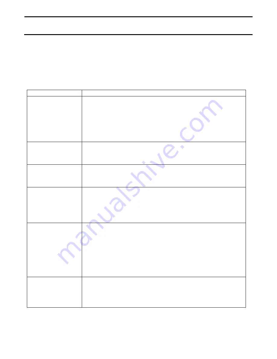
2.  The following table describes each of the settings required to create a 

configuration. The table on the following page is recommended default 
settings based on which control valve is used. 

Setting Name 

Description 

Control Valve 

Configuration 


Inline Servo: 

Rate control is achieved through actuating a control 

valve in the solution hose that goes to the booms. When the valve 
opens flow increases and when the valve closes, flow decreases.


Bypass Servo

: Rate control is achieved through actuating a control 

valve in the return line to the solution tank. When the valve opens, the 
flow decreases and when the valve closes the flow increases. 


Valve Response 1 


Determines the speed of the servo valve when product control error 
exceeds the 

Response Threshold

 setting. Decreasing the value will 

cause the servo valve to run slower 


Valve Response 2 


Determines the speed of the servo valve when product control error is 
less than the 

Response Threshold

 setting. Decreasing the value will 

cause the servo valve to run slower. 


Allowable Error 


Determines the percent of error that is allowed prior to the product 

control system making any flow rate corrections.2 % – 3 % is the normal 

dead band setting range. Too low of a setting will cause the control 

system to continually hunt for the target application rate. Too high of a 

setting will cause excessive application error. 


Response 

Threshold 


Determines where the control system switches between using


Valve 

response 1 and Valve response 2 speed settings. Decreasing this value 
will have the overall effect of speeding up servo valve response. 
Increasing this value will have the overall effect of slowing down servo 
valve response. 


NOTE: Leaving all other valve control settings at the default 
value and making a small adjustment to this setting is usually 
all that is required to fine-tune the control system. 


Flow Meter Cal 


This is the number pulses per 10 gallons of product flow thru the Raven 

flow meter. The Ag Leader Display requires pulses per gallon for 

calibration. To calculate the appropriate values divide the Raven 

calibration number by 10 before entering into the Ag Leader Display. 


Summary of Contents for 4200140

Page 1: ...Switch 4001507 1 Accu Flow Control Valve Adapter Optional 4001635 1 Cable ISOBUS Breakout Type 1 4002597 008 1 CAN Implement Switch Cable 4002658 1 Liquid Rate Control Module 4002861 1 Local CAN Term...

Page 2: ...safe correct installation and operation of this product CAUTION will alert you to situations that will impact the physical safety of you or others IMPORTANT will alert you to the potential for damage...

Page 3: ...06375 Rev B February 2015 Page 3 of 15 Common Components This section contains illustrations of components common to all DirectCommand installations Their purpose is to ensure proper identification an...

Page 4: ...Ag Leader Technology DirectCommand Installation Raven Accu Flow ISO Kit Page 4 of 15 February 2015 PN 2006375 Rev B Component and Cable Layout...

Page 5: ...r Display DirectCommand components and flow meter from electrical system when welding on equipment or jump starting unit to prevent component damage due to power surges or excessive current IMPORTANT...

Page 6: ...for the Liquid Rate Control Module PN 4002861 Make sure to choose a mounting location that is big enough for Liquid Swath Control Module PN 4002862 if it is needed Mount modules where they will be pr...

Page 7: ...f the ISOBUS Breakout Cable to the 6 pin Metripack receptacle of the Active Terminator Cable Imp PN 4003122 8 Connect the Local CAN Terminating Receptacle PN 4002871 and the Local CAN Terminating Plug...

Page 8: ...ific to the Accu Flow Control Valves with a 4 position ConXall Connection If this DirectCommand system is installed using a control valve that does not have 4 position ConXall Connector go to step 11...

Page 9: ...4 pin Deutsch receptacle of the Auxiliary Valve Harness from Table A above to the mating plug on the Flow Control Channel Cable 8 Tee the gray 2 pin connectors of the Auxiliary Valve Harness into the...

Page 10: ...4003970 6 12 Connect the 2 position molded connector of the adapter cable to the Accu Flow Control Valve 13 Connect the spade terminal with the black wire to the white wire coming from the Accu Flow...

Page 11: ...003949 6 to the gray 12 pin receptacle of the Liquid Swath Control Module PN 4002862 7 Connect the gray 2 pin receptacle on the 12 Boom Section Cable to one of the gray 2 pin plugs of the ISOBUS Imple...

Page 12: ...s kit on an implement that is raised out of the ground when not applying it is recommended to install an optional Implement Switch This will prevent the controller from turning on product flow when th...

Page 13: ...plug the 3 pin Weatherpack Shroud labeled NORMALLY CLOSED on the Implement Switch into the 3 pin Weatherpack Tower of the Implement Switch Extension Cable PN 2000453 X Begin routing the Extension Cab...

Page 14: ...etermines the speed of the servo valve when product control error is less than the Response Threshold setting Decreasing the value will cause the servo valve to run slower Allowable Error Determines t...

Page 15: ...30 gpm Two Valve System STANDARD VALVE Inline Servo 100 24 5 Raven Flow Control Valve 3 4 STANDARD VALVE Inline Servo or Bypass Servo 100 24 1 Raven Flow Control Valve 3 4 FAST VALVE Inline Servo or B...

Reviews: