background image

DirectCommand

 Installation 

Raven Accu-Flow ISO Kit


Ag Leader Technology 


PN: 2006375 Rev. B 

February 2015 

Page 7 of 15


5.  Plug the 24-pin FCI connector of the ISOBUS Breakout Cable, 

PN: 4002597-008 to the mating connector of the Liquid Rate 
Control Module. 


6.  Connect the 6-pin Metripack plug of the ISOBUS Implement 

Cable PN: 4004110-12 to the 6-pin Metripack receptacle of the 
ISOBUS Breakout Cable. 
 

7.  Connect the 6-pin Metripack plug of the ISOBUS Breakout 

Cable to the 6-pin Metripack receptacle of the Active Terminator 
Cable (Imp), PN: 4003122. 
 

8.  Connect the Local CAN Terminating Receptacle, PN: 4002871 

and the Local CAN Terminating Plug, PN: 4002870 to the 
mating connectors of the ISOBUS Breakout Cable. 


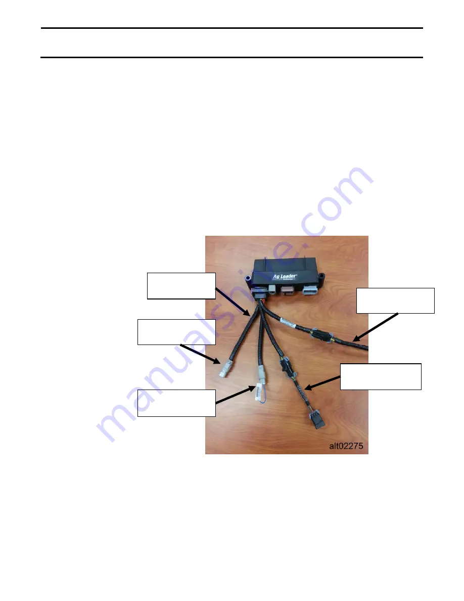
Liquid Rate Control Module with ISOBUS Cabling


9.  Route the round metal connector end of the ISOBUS Implement 

Cable towards the tractor. 

10. Route cable to avoid any sharp edges and pinch points.


Bundle 

up all excess cable and tie with zip-ties.


Local CAN 

Terminating Rec. 

Local CAN 

Terminating Plug 

ISOBUS 

Breakout Cable 

ISOBUS 

Implement Cable 

Active Terminator 

Cable 

Summary of Contents for 4200140

Page 1: ...Switch 4001507 1 Accu Flow Control Valve Adapter Optional 4001635 1 Cable ISOBUS Breakout Type 1 4002597 008 1 CAN Implement Switch Cable 4002658 1 Liquid Rate Control Module 4002861 1 Local CAN Term...

Page 2: ...safe correct installation and operation of this product CAUTION will alert you to situations that will impact the physical safety of you or others IMPORTANT will alert you to the potential for damage...

Page 3: ...06375 Rev B February 2015 Page 3 of 15 Common Components This section contains illustrations of components common to all DirectCommand installations Their purpose is to ensure proper identification an...

Page 4: ...Ag Leader Technology DirectCommand Installation Raven Accu Flow ISO Kit Page 4 of 15 February 2015 PN 2006375 Rev B Component and Cable Layout...

Page 5: ...r Display DirectCommand components and flow meter from electrical system when welding on equipment or jump starting unit to prevent component damage due to power surges or excessive current IMPORTANT...

Page 6: ...for the Liquid Rate Control Module PN 4002861 Make sure to choose a mounting location that is big enough for Liquid Swath Control Module PN 4002862 if it is needed Mount modules where they will be pr...

Page 7: ...f the ISOBUS Breakout Cable to the 6 pin Metripack receptacle of the Active Terminator Cable Imp PN 4003122 8 Connect the Local CAN Terminating Receptacle PN 4002871 and the Local CAN Terminating Plug...

Page 8: ...ific to the Accu Flow Control Valves with a 4 position ConXall Connection If this DirectCommand system is installed using a control valve that does not have 4 position ConXall Connector go to step 11...

Page 9: ...4 pin Deutsch receptacle of the Auxiliary Valve Harness from Table A above to the mating plug on the Flow Control Channel Cable 8 Tee the gray 2 pin connectors of the Auxiliary Valve Harness into the...

Page 10: ...4003970 6 12 Connect the 2 position molded connector of the adapter cable to the Accu Flow Control Valve 13 Connect the spade terminal with the black wire to the white wire coming from the Accu Flow...

Page 11: ...003949 6 to the gray 12 pin receptacle of the Liquid Swath Control Module PN 4002862 7 Connect the gray 2 pin receptacle on the 12 Boom Section Cable to one of the gray 2 pin plugs of the ISOBUS Imple...

Page 12: ...s kit on an implement that is raised out of the ground when not applying it is recommended to install an optional Implement Switch This will prevent the controller from turning on product flow when th...

Page 13: ...plug the 3 pin Weatherpack Shroud labeled NORMALLY CLOSED on the Implement Switch into the 3 pin Weatherpack Tower of the Implement Switch Extension Cable PN 2000453 X Begin routing the Extension Cab...

Page 14: ...etermines the speed of the servo valve when product control error is less than the Response Threshold setting Decreasing the value will cause the servo valve to run slower Allowable Error Determines t...

Page 15: ...30 gpm Two Valve System STANDARD VALVE Inline Servo 100 24 5 Raven Flow Control Valve 3 4 STANDARD VALVE Inline Servo or Bypass Servo 100 24 1 Raven Flow Control Valve 3 4 FAST VALVE Inline Servo or B...

Reviews: