background image

VENTILATION AND COMBUSTION AIR
REQUIREMENTS

A permanent air supply must be provided in accor-
dance with Building Regulation ADJ and BS 8303.

Please refer to Building Regulations Part J to deter-
mine the size of permanent air vent required, as fol-
lows:

Install where draft stabilizer is fitted:

Permanently open vents as below:
If design air permeability >5.0m

3

/(h.m

2

) then

300mm

2

/kW for first 5kW of appliance rated output

850mm

2

/kW for balance of appliance rated output

If design air permeability <5.0m

3

/(h.m

2

) then

850mm

2

/kW of appliance rated output (4)

Install where no draft stabilizer is fitted:

Permanently open vents as below:
If design air permeability >5.0m

3

/(h.m

2

) then

550mm

2

/kW of appliance rated output above 5kW

If design air permeability <5.0m

3

/(h.m

2

) then

550mm

2

per kW of appliance rated output (4)

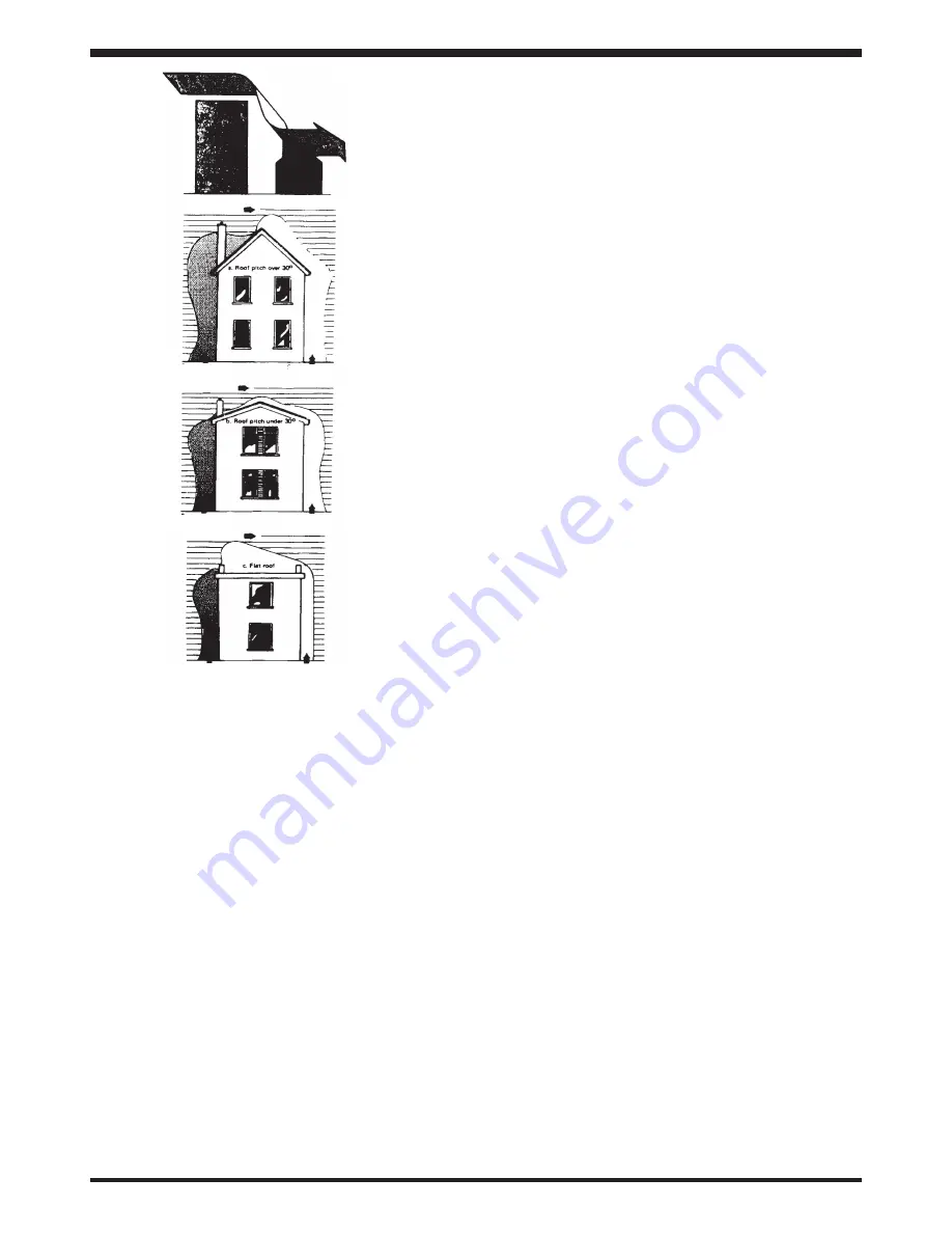
Direction of wind

Direction of wind

Direction of wind

Pressure zone

Pressure zone

Suction zone

Suction zone

Pressure zone

Suction zone

Fig 2

If there is another appliance using air fitted in the
same or adjacent room, it will be necessary to 
provide an additional air supply.

All materials used in the manufacture of air vents
should be such that the vent is dimensionally stable,
corrosion resistant, and no provision for closure. Air
inlet grills should be positioned so they do not
become liable to blockage.

The effective free area of any vent should be ascer-
tained before installation. The effect of any grills
should be allowed for when determining the effective
free area of any vent.

Air vents direct to the outside of the building should
be located so that any air current produced will not
pass through normally occupied areas of the room.
An air vent outside the building should not be locat-
ed less than the dimensions specified within the
Building Regulations and B.S. 8303: Part 1 from any
part of any flue terminal. These air vents must also
be satisfactorily fire proofed as per Building
Regulations and B.S. 8303: Part 1.

Air vents in internal walls should not communicate
with bedrooms, bedsits, toilets, bathrooms or rooms
containing a shower.

Air vents traversing cavity walls should include a
continuous duct across the cavity. The duct should
be installed in such a manner as not to impair the
weather resistance of the cavity.
Joints between air vents and outside walls should be
sealed to prevent the ingress of moisture. Existing
air vents should be of the correct size and unob-
structed for the appliance in use. If there is an
extraction fan fitted in adjacent rooms where this
appliance is fitted, additional air vents may be
required to alleviate the possibility of spillage of
products of combustion from the appliance/flue
while the fan is in operation. Refer to B.S. 8303 Part
1.

Where such an installation exists, a test for spillage
should be made with the fan or fans and other appli-
ances using air in operation at full rate, (i.e. extrac-
tion fans, tumble dryers) with all external doors and
windows closed.

If spillage occurs following the above operation, an
additional air vent of sufficient size to prevent this
occurrence should be installed.

4

Summary of Contents for ELLESMERE 4K

Page 1: ...n aged or infirm persons should be supervised at all times and should not be allowed to touch the hot working surfaces while in use or until the appliance has thoroughly cooled When using the stove in situations where children aged and or infirm persons are present a fireguard must be used to prevent accidental contact with the stove The fireguard should be manufactured in accordance with BS 8423 ...

Page 2: ...stibles 5 14 Stove Dimensions 7 15 Technical Data 8 16 Air Controls 9 17 Recommended Fuels 9 18 Riddling 10 19 Refuelling 10 Refuelling onto a low firebed 10 Fuel overloading 10 Operation with door left open 10 20 Dampers Air Controls left open 10 21 De Ashing 10 22 Disposal of Ash 10 23 Maintenance 11 24 Chimney Cleaning 11 25 Important Notes 11 26 Lighting 12 27 Fire Safety 12 28 CO Alarms 13 29...

Page 3: ...r is installed by a Competent Person registered with a Government approved Competent Persons Scheme HETAS Ltd operate such a Scheme and a listing of their Registered Competent Persons can be found on their website at www hetas co uk The installation must be completed in accordance with current National and European Standards and Local Codes It should be noted that the requirements and these public...

Page 4: ...he flexible flue liner The chimney flue should be designed to allow for cleaning of the stove use pipes with cleaning doors where necessary Avoid the use of 90 degree elbows use 2 x 45o bends instead Horizontal runs of flue pipe should be avoided where it is unavoidable the maximum permitted horizontal run is 150mm The chimney flue must have the necessary clearance distance from combustible materi...

Page 5: ... for when determining the effective free area of any vent Air vents direct to the outside of the building should be located so that any air current produced will not pass through normally occupied areas of the room An air vent outside the building should not be locat ed less than the dimensions specified within the Building Regulations and B S 8303 Part 1 from any part of any flue terminal These a...

Page 6: ...o should smoke or fumes be emitted from the stove The customer should be warned to use a fire guard to BS 8423 2002 in the presence of children aged and or infirm persons LOCATION There are several conditions to be considered in selecting a location for your stove A Allowances for proper clearances to combustibles of the stove and flue pipes B The product must be installed on a non combustible hea...

Page 7: ...REDUCED CLEARANCE TO COMBUSTIBLES With Heatshield See Figs 4a 4b 4c Fig 4a Fig 4b Fig 4c 6 Side wall to stove 28 700mm Back wall to stove 28 700mm Corner 25 635mm Mantle clearance 25 635mm ...

Page 8: ...7 STOVE DIMENSIONS Fig 5 Note Dimensions stated are in milimeters and may be subject to a slight variation 4kW 6kW 5kW ...

Page 9: ...peration e g intensive burning high fuel consumption and can also lead to permanent damage to the stove ELLESMERE STOVES TECHNICAL DATA 4 kW 5kW 6kW FUEL WOOD ANCIT WOOD ANCIT WOOD ANCIT Nominal Output Room 4 5 3 8 5 2 5 0 5 9 6 4 Typical refuelling intervals to obtain nominal outputs Hour 75 1 75 1 75 1 Fuel Gas Mass Flow g s 3 3 2 7 4 3 9 4 3 9 Flue Gas Temp at Nominal Output oC 263 190 263 245 ...

Page 10: ...re to provide a little primary to maintain the fire When burning coal the air control should always be to the right of centre On initial light up the lever should be pushed slightly to the right and pushed fully in providing under grate air fully while still pro viding some window wash air to maintain a clear viewing glass See Fig 6 To engage the operating tool onto the air control rotate the tool...

Page 11: ... on the left side of the stove While keeping the tool pushed in rotate in a circular motion which will cause the individual grate castings to rise and fall dislodging the ash into the ashpan See Fig 9 Remember to reset the controls after refuelling DAMPERS AIR CONTROLS LEFT OPEN Operation with the air controls or appliance dampers open can cause excess smoke The appliance must not be operated with...

Page 12: ...ick Lift the stainless steel baffle and catch a back brick on the top edge and tilt it forward to remove it Lift and hold the stainless steel baffle while catching the remaining back brick on the top edge and tilting it forward to remove it 11 WARNING NOTE Properly installed operated and maintained the stove will not emit fumes into the dwelling Occasional fumes from de ashing and re fuelling may ...

Page 13: ...S LIGHTING Before lighting the stove check with the installer that the installation work and commissioning checks described in the installation instructions have been carried out correctly and that the chimney has been swept clean is sound and free from any obstructions As part of the stoves commissioning and handover the installer should demonstrate how to operate the stove correctly WARNING The ...

Page 14: ...baffle on the right hand side while holding it up catch the top edge of the right hand side brick and lower it into the stove to allow for removal Remove the cast iron baffle cleaning door by lifting it forward while sliding it to the right clear of the left hand side brick this will allow the back edge be low ered so the baffle is almost vertical allowing it be manoeuvred through the door opening...

Page 15: ...ve the broken glass c Clean the glass recess in the door d Place the glass into the door recess and replace the four corner clips e Tighten screws f Replace glass only with ceramic glass 5mm thick PROLONGED PERIODS OF NON USE If the stove is to be left unused for a prolonged peri od of time then it should be given a thorough clean to remove ash and unburned fuel residues To enable a good flow of a...

Page 16: ... PLATE 177A_0000_161 14 HINGE PIN STOP 177A_0000_171 15 SHELL BRACKET 177A_0000_181 16 ASHPIT COVER 177A_0000_211 17 RIDDLING ROD RETAINER 177A_0000_221 18 STOVE SHELL 177A_0100_001 19 FIRE DOOR 177A_0300_011 20 HINGE LINK 177A_0300_021 21 DOOR LATCH 177A_0300_041 22 GLASS 177A_0300_051 23 GLASS CLIP 177A_0300_061 24 DOOR HANDLE 177A_0300_071 25 WASHER 177A_0300 _081 26 HOB 177A_0600_001 27 RIDDLI...

Page 17: ... PLATE 177A_0000_161 14 HINGE PIN STOP 177A_0000_171 15 SHELL BRACKET 177A_0000_181 16 ASHPIT COVER 177A_0000_211 17 RIDDLING ROD RETAINER 177A_0000_221 18 STOVE SHELL 177B_0100_001 19 FIRE DOOR 177B_0300_011 20 HINGE LINK 177B_0300_021 21 DOOR LATCH 177A_0300_041 22 GLASS 177B_0300_051 23 GLASS CLIP 177A_0300_061 24 DOOR HANDLE 177A_0300_071 25 WASHER 177A_0300 _081 26 HOB 177B_0600_001 27 RIDDLI...

Page 18: ... PLATE 177A_0000_161 14 HINGE PIN STOP 177A_0000_171 15 SHELL BRACKET 177A_0000_181 16 ASHPIT COVER 177A_0000_211 17 RIDDLING ROD RETAINER 177A_0000_221 18 STOVE SHELL 177A_0100_001 19 FIRE DOOR 177C_0300_011 20 HINGE LINK 177B_0300_021 21 DOOR LATCH 177A_0300_041 22 GLASS 177A_0300_051 23 GLASS CLIP 177A_0300_061 24 DOOR HANDLE 177A_0300_071 25 WASHER 177A_0300 _081 26 HOB 177C_0600_001 27 RIDDLI...

Page 19: ...ating Replace the grate and do not allow ash pan to overfill Operation with the ash door open While the stove is in operation the door should be closed Burning non approved fuel Burn correct fuel Glass Sooting Up Air wash not working Open the air wash control Moisture content of fuel too high Ensure fuel is sufficiently dry Insufficient flue draught Seek professional chimney advice Air controls se...

Page 20: ...nstallation Final cure of the painted surfaces This odour is unpleasant but not toxic It is best advised to ventilate the room and leave unoccupied Incorrect sealant used All flue Joints must be sealed with fire cement only Insufficient flue draught Seek professional chimney advice Water In Base Of Stove Condensation on light up It is acceptable to have a little condensa tion on start up when the ...

Reviews: