background image

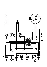
G1112

FORC

ED

CON

VECTIO

N

OVEN

WIRING

DIAGR

AM

(BW2150

1/H)

Summary of Contents for Falcon G1102

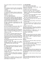
Page 1: ...EARTHED On completion of the installation these instructions should be left with the Engineer in Charge for reference during servicing Further to this The Users Instructions should be handed over to...

Page 2: ...nt installer MUST be employed The appliance flue discharges vertically through the grill at the rear of the hob and there must be no direct connection of the flue to any mechanical extraction system o...

Page 3: ...heat exchangers and around the cooking space whilst the smaller externally mounted fan serves to cool the motor and control gear compartment SECTION 2 ASSEMBLY and COMMISSIONING 2 1 ASSEMBLY 2 1 1 G11...

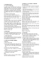
Page 4: ...of base of top unit carefully against this back flange d Fix the top unit to the bottom one using the M6 x 50mm hexagon screws provided Two at the front corners of the base and two at the back through...

Page 5: ...described in the accompanying User s Instructions At this stage take care not to touch live connections which are now exposed behind the withdrawn oven control panel c Check all connections for gas so...

Page 6: ...cover over adjusting screw 2 5 6 Propane Models Only a Remove plastic cap and turn screw NO PR fully clockwise b Adjust pressure regulator until a pressure of about 12mbar is obtained on outlet c Rep...

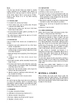
Page 7: ...it is the correct way up The locating tabs automatically spring into position 3 2 6 Timer Remove push on connections at the rear Pull off control knob and undo the screws holding timer to panel Replac...

Page 8: ...e assemble in reverse order Note Fit injector to groove in brass nut before inserting it into hole in body of pilot assembly 3 8 REMOVAL and CLEANING of BURNERS 3 8 1 Oven Burner a Withdraw control pa...

Page 9: ...tion 3 2 1 b Remove buzzer connections c Remove single screw fixing buzzer to panel d Replace in reverse order 3 14 CAPACITOR To replace proceed as follows a Withdraw control panel as Section 3 2 1 b...

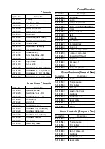
Page 10: ...tical 531740300 Door Seal Vertical 531740310 Fan Guard 531743020 Oven Lamp Glass 531740430 Fuse 5A 531740440 Indicator Lamp Amber 531740450 Indicator Lamp Red 531740460 Power On Off Switch 531740470 T...

Page 11: ...G 1 1 1 2 F O R C E D C O N V E C T I O N O V E N W I R I N G D I A G R A M B W 2 1 5 0 1 H...

Reviews: