Assembly Instructions
33
/
42
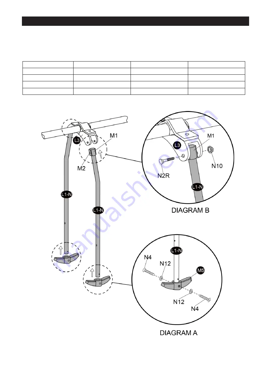
Step 13
– Glide Ride Assembly (continued)
➢
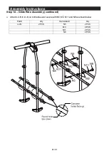
Insert L1-N (straight end) into M5 and secure with N4 and N12 on both sides as shown in DIAGRAM A.
➢
Attach L1-N to L3 on both sides and secure with N2R and N10 as shown in DIAGRAM B.
Part#
Qty
Hardware#
Qty
L1-N
2 PCS
N4
4 PCS
M5
2 PCS
N12
4 PCS
N2R
2 PCS
N10
2 PCS
Summary of Contents for 164176
Page 12: ...12 42 Complete Product View ...


