background image

29

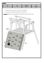
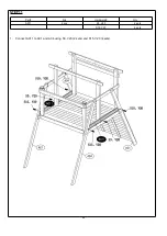
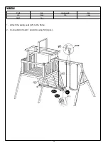
STEP 10

Part#

Qty

Hardware#

Qty

U4

12 pcs

B28,V2,V31

24 sets

S6

60 pcs

1. Connect AC18, AC19 and AC20 to AC1 and AC4 using S6 (60 pcs).

2. Connect U4 to AC19 and AC20 using B28, V2 and V31 (24 sets).

Helpful Hint: Make sure the climbing board is flush with the fort floor boards before securing.

Summary of Contents for Lookout Ridge 160395

Page 1: ...S FOR RESIDENTIAL USE ONL Y DO NOT RETURN TO THE STORE For replacement parts please call 1 866 370 2131 Monday Friday 9 00 AM 5 00 PM Eastern Time Customer Service 888 922 2336 7 00 am to 12 00 am CST daily Live Chat at www academy com Email customerservice academy com Please keep this instruction manual for future reference ...

Page 2: ...S Consumer Product Safety Commission s Outdoor Home Playground Safety Handbook recommends to install and maintain the playground equipment over at least 9 inches of wood chips mulch or shredded rubber for equipment up to 8 feet high or sand or pea gravel for equipment no more than 5 feet high as shock absorbing material Dirt and grass which are the most prevalent surfaces under home playground equ...

Page 3: ...ARTS LIST 18 COMPONENT PARTS LIST 19 ASSEMBLY AND INSTALLATION INSTRUCTIONS 20 HELPFUL TIPS 46 PRODUCT WARRANTY 47 Note Before beginning assembly of product make sure all parts are present Compare parts with package content list and hardware contents If any part is missing or damaged do not attempt to assemble the unit Contact customer service for replacement parts TABLE OF CONTENTS ...

Page 4: ...ipment at all times Unpack all parts Take a completed inventory of all parts and hardware using the parts and hardware lists in the following pages If any parts are missing do not return to the store Please call customer service toll free number listed on the cover page for assistance Store the product back in the original box and do not begin to install until all parts are obtained Never add extr...

Page 5: ...set to become loose and unstable Find a location where the equipment can be placed more than six 6 feet from any structure or obstruction ex electrical wires branches house fence garage The safe play area refers to a zone extending six 6 feet beyond the swing set on all sides including the space above the swing set The safe play area must be free of all structures landscaping trees and branches ro...

Page 6: ...and holding on to the swing chains DO NOT allow children to jump off the equipment while it is in motion ALWAYS come to a full stop before dismounting ALWAYS dress children appropriately for playing e g wear well fitted rubber sole shoes and remove loose or sharp items such as jewelry hair accessories scarves ponchos that may become entangled in the equipment or cause injuries ALWAYS make sure chi...

Page 7: ...ately properly store the set or restrict access by users until the condition is resolved Verify that the suspended climbing ropes chain or cable are secured at both ends and tightened so that there is no loose ropes chain or cable hanging that can result in choking hazard WEATHER CONDITIONS DO NOT use this equipment if the swing seat slide or other parts are wet Use the swing set only when the par...

Page 8: ...25 4CM 11 27 94CM Wood Chips 6 15 25CM 7 17 8CM 12 30 5CM Fine Sand 5 12 7CM 5 12 7CM 9 22 86CM Fine Gravel 6 15 25CM 7 17 8CM 10 25 4CM However it should be recognized that all injuries due to falls cannot be prevented no matter what surfacing material is used We recommend that a shock absorbing material should extend a minimum of 6ft in all directions from the perimeter of stationary equipment s...

Page 9: ...ceive the least direct sunlight SELECT PROTECTIVE SURFACING One of the most important things you can do to reduce the likelihood of serious head injuries is to install shock absorbing protective surfacing under and around your play equipment The protective surfacing should be applied to a depth that is suitable for the equipment height in accordance with ASTM F1292 There are different types of sur...

Page 10: ... manufacturer for a report showing that the product has been tested to the following safety standard ASTM F1292 Standard Specification for Impact Attenuation of Surfacing Materials within the Use Zone of Playground Equipment This report should show the specific height for which the surface is intended to protect against serious head injury This height should be equal to or greater than the fall he...

Page 11: ...se wood mulch chips shredded rubber mulch or engineered wood fiber for equipment up to 8 feet high Use sand pea gravel or mulch products listed above for play equipment up to 5 feet high or Use surface mats tested to provide impact protection equal to or greater than the height of the play equipment Equipment Maintenance Periodically check nuts bolts caps swing seats suspension ropes chains and ca...

Page 12: ...repellent exterior sealant or boiled linseed oil Do NOT paint varnish or finish rungs with any substance that may reduce your child s ability to firmly grasp or step on the rungs Swing hangers Inspect for correct installation Assure the bend of the swing hanger is positioned tightly against the stop washer and the ladder or swing beam The axis of the swing hanger bushing must be perpendicular to t...

Page 13: ...ers Replace if they are loose cracked or missing Rake and check depth of loose fill protective surfacing materials to prevent compaction and to maintain appropriate depth Replace as necessary ONCE A MONTH DURING PLAY SEASON Lubricate all metallic moving parts per manufacturer s instructions Check all moving parts including swing seats ropes cables and chains for wear rust or other deterioration Re...

Page 14: ...13 COMPLETE PRODUCT VIEW FRONT VIEW OF COMPLETE PRODUCT BACK VIEW OF COMPLETE PRODUCT ...

Page 15: ...14 TOOLS NOT INCLUDED These are the tools that are generally required for installation These tools are not included in the purchased packaging unless stated below TOOLS INCLUDED ...

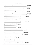
Page 16: ...15 WOOD PARTS LIST ...

Page 17: ...16 WOOD PARTS LIST ...

Page 18: ...17 WOOD PARTS LIST ...

Page 19: ...at you get the right hardware in the correct place when assembling the unit You can use a ruler to measure your hardware or you can compare the hardware to the hardware identification page NOTES 1 Do not include bolt head when measuring length of bolt 2 Include full length of deck screw when measuring ...

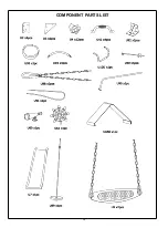
Page 20: ...19 COMPONENT PARTS LIST ...

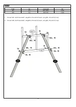
Page 21: ...sets AC7 1 pc AC8 1 pc AC28 1 pc 1 Connect AC2 to AC5 AC7 and AC8 using S3 and V20 4 sets using B7L V8 and V9 2 sets 2 Connect AC28 to AC5 AC7 and AC8 using S3 and V20 6 sets Helpful Hint Do not fully tighten Make sure the pre drilled holes align correctly according to the image ...

Page 22: ...dware Qty AC1 1 pc B3L V8 V9 6 sets AC4 1 pc B4 V8 V9 2 sets 1 Connect AC1 to AC2 and AC28 using B3L V8 and V9 3 sets using B4 V8 and V9 1 set 2 Connect AC4 to AC2 and AC28 using B3L V8 and V9 3 sets using B4 V8 and V9 1 set ...

Page 23: ...L V8 V9 2 sets AC6 1 pc S3 V20 10 sets AC7 1 pc AC8A 1 pc AC27 1 pc 1 Connect AC3 to AC6 AC7 and AC8A using S3 and V20 4 sets using B7L V8 and V9 2 sets 2 Connect AC27 to AC6 AC7 and AC8A using S3 and V20 6 sets Helpful Hint Do not fully tighten ...

Page 24: ...dware Qty AC1 1 pc B3L V8 V9 6 sets AC4 1 pc B4 V8 V9 2 sets 1 Connect AC1 to AC3 and AC27 using B3L V8 and V9 3 sets using B4 V8 and V9 1 set 2 Connect AC4 to AC3 and AC27 using B3L V8 and V9 3 sets using B4 V8 and V9 1 set ...

Page 25: ...4 2 pcs 1 Connect AC9 to AC5 and AC6 using B4 V8 and V9 4 sets 2 Connect AC10 to AC5 and AC6 using B5 V8 and V9 4 sets 3 Connect AC14 to AC5 and AC6 using B4 V8 and V9 4 sets 4 Connect AC14 to AC7 using B4 V8 and V9 4 sets Helpful Hint Make sure that the legs are parallel with each other ...

Page 26: ...25 STEP 6 Part Qty Hardware Qty AC9 1 pc B4 V8 V9 4 sets AC13 1 pc B5 V8 V9 4 sets 1 Connect AC9 to AC8 and AC8A using B4 V8 and V9 4 sets 2 Connect AC13 to AC8 and AC8A using B5 V8 and V9 4 sets ...

Page 27: ...26 STEP 7 Part Qty Hardware Qty AC21 2 pcs S3 V20 4 sets 1 Connect AC21 to AC9 using S3 and V20 4 sets Helpful Hint Make sure the small pre drilled holes face upward on A21 ...

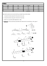
Page 28: ...art Qty Hardware Qty AC22 1 pc S6 70 pcs AC23 13 pcs AC24 1 pc AC25 1 pc AC26 1 pc 1 Connect AC22 AC26 AC23 AC24 AC25 to the play fort using S6 70 pcs Helpful Hint Place all boards before securing to the structure ...

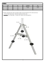
Page 29: ...Qty Hardware Qty AC18 3 pcs S5 30 pcs AC19 6 pcs AC20 6 pcs AC39 2 pcs 1 Connect AC39 to AC18 AC19 and AC20 using S5 30 pcs Helpful Hint Make sure that you lay the boards A18 A20 on a flat surface the distance is 18 3 ...

Page 30: ...s B28 V2 V31 24 sets S6 60 pcs 1 Connect AC18 AC19 and AC20 to AC1 and AC4 using S6 60 pcs 2 Connect U4 to AC19 and AC20 using B28 V2 and V31 24 sets Helpful Hint Make sure the climbing board is flush with the fort floor boards before securing ...

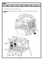
Page 31: ...30 STEP 11 Part Qty Hardware Qty AC11 2 pcs S3 V20 2 sets S15 V20 4 sets 1 Connect AC11 to AC1 and AC4 using S3 V20 2 sets and S15 V20 4 sets ...

Page 32: ...STEP 12 Part Qty Hardware Qty AC35 7 pcs S5 14 pcs 1 Connect AC35 to AC28 and AC11 using S5 14 pcs Helpful Hint make sure AC35 boards are no more than 2 8 and 2 86 apart from each other as show as DIAGRAM ...

Page 33: ...32 STEP 13 Part Qty Hardware Qty AC35 7 pcs S5 14 pcs 1 Connect AC35 to AC27 and AC11 using S5 14 pcs Helpful Hint Make sure AC35 are no more than 2 8 and 2 86 apart from each other as show as DIAGRAM ...

Page 34: ...1 pc S4 V20 8 sets AC12A 1 pc B1 V8 V9 4 sets AC15 2 pcs 1 Connect AC12 to AC5 and AC7 using S4 V20 4 sets 2 Connect AC12A to AC6 and AC7 using S4 V20 4 sets 3 Connect AC15 to AC14 using B1 V8 and V9 4 sets Helpful Hint Please note the A B ...

Page 35: ...34 STEP 15 Part Qty Hardware Qty AC16 2 pcs S6 6 pcs AC17 1 pc 1 Connect AC16 to AC14 using S6 4 pcs 2 Connect AC17 to AC15 using S6 2 pcs ...

Page 36: ...c S3 V20 6 sets AC33 1 pc AC34 1 pc Insert B9 V8 through AC33 AC31 and AC32 and fasten with V8 V9 2sets on the other end of screw 1 Connect AC34 to AC32 AC31 and AC33 using S3 and V20 6 sets Helpful Hint Do not fully tighten Go back and re tighten when fully assembled ...

Page 37: ...mer the square head rivets V4 into the pre drilled holes as shown below 1 Connect U2 to AC29 using B4 V24 and V24 V9 2 sets 2 Connect U2 to AC30 using B4 V24 and V24 V9 2 sets 3 Attach V7 V1 and V6 to AC29 and AC30 7 sets Helpful Hint Confirm what side of the beam will be attached to the main structure of the play set ...

Page 38: ... U3 2 pcs B1 V24 V9 4 sets B4 V24 V9 4 sets ATTACH TWO PERSON FLYING SAUCER IN THE FOLLOWING ORDER 1 Attach U2 to AC12 on both sides using B1 V24 and V9 4 sets 2 Attach U3 to AC29 and AC31 on both sides using B4 V24 and V24 V9 4 sets ...

Page 39: ...38 STEP 19 Part Qty Hardware Qty U5 2 pcs S6 4 pcs AC41 1 pc 1 Attach the swing seat U5 to the frame 2 Connect AC41to AC1 and AC4 using S6 4 pcs ...

Page 40: ...art Qty Hardware Qty AC36 2 pcs B7 V8 V9 6 sets AC37 1 pc AC38 1 pc 1 Connect AC37 to AC36 using B7 V8 and V9 4 sets 2 Connect AC38 to AC36 using B7 V8 and V9 2 sets Helpful Hint Note the placement of AC37 and AC38 ...

Page 41: ...s U92 2 pcs B4 V24 V9 1 set B6 V24 V9 2 sets S1 V2 4 sets 1 Attach U2 to AC12A on both sides using B1 V24 and V9 4 sets 2 Attach U92 to AC30 using B4 V24 and V24 V9 1 set to AC30 and AC36 using S1 and V2 4 sets to AC37 using B6 V24 and V9 2 sets on both sides ...

Page 42: ...LYING SAUCER IN THE FOLLOWING ORDER 1 Slide the smaller ends of U94 tubes into the pockets of flying saucer U93 Connect the four tubes together Align the holes with the round holes face down 2 Connect the chain U88 to the flying saucer insert the end with shorter screw and secure with V6 and V18 4 sets ...

Page 43: ...9 1 pc V2 4 pcs U91 1 pc 1 Attach the flying saucer to the frame 2 Attach the U89 to the frame 3 Attach the U91 rope to AC10 and AC41 Tie a knot at one end of the rope before pulling through AC10 and AC41 4 Attach U42 to AC5 and AC6 using S1 and V2 4 sets ...

Page 44: ...OWING ORDER 1 Attach U90 to AC13 using B1 V1 and V9 2 sets 2 Attach U42 to AC8 and AC8A using S1 and V2 4 sets 3 Connect U658 on the top using S9 8 pcs Helpful Hint Fireman Pole will need to be secured in the ground first to properly align with the structure of the play set The pole has an angle to assist with inserting it into the ground ...

Page 45: ...2 sets ATTACH SLIDE TO THE SWINGSET IN THE FOLLOWING ORDER 1 Attach U10D to U7 using S18 V18 and V3 4 sets 2 Connect U7 to AC25 using B28 V2 and V31 2 sets Helpful Hint Bottom of slide will need to be raised up in order to align the floorboards and the top of slide before securing ...

Page 46: ... Connect U60 to AC8A using L12 4 pcs Connect U61 to AC35 using S4 1 set 3 Connect A40 to AC25 using S5 4 pcs IMPORTANT BEFORE ALLOWING CHILDREN TO PLAY ON THE EQUIPMENT THE ANCHORS PROVIDED MUST BE INSTALLED ALSO PLEASE GO OVER THE ENTIRE UNIT AND MAKE SURE ALL SCREWS ARE TIGHTENED ALL THE WAY AND INSPECT THE ENTIRE UNIT TO ENSURE THE EQUIPMENT IS STABLE AND PROPERLY INSTALLED BEFORE ALLOWING CHIL...

Page 47: ...46 Helpful Tips Regularly check play set for wasp s nests before allowing children to use It is best practice to coat your play set with a water sealant to extend the longevity of the product ...

Page 48: ...age caused by the use of other than genuine parts are not covered by this warranty This warranty shall be effective from the date of purchase as shown in the purchaser receipt This warranty is valid for the original consumer purchaser only and excludes industrial commercial or business use of the product product damage due to shipment or failure which results from alteration product abuse or produ...

Reviews: