background image


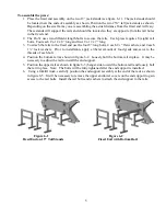
             Figure 6-3   


            Figure 6-4 


    Press with Both Rails  


                      Fixed End with Rail Bolts 


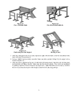
                               Figure 6-5 


            Figure 6-6 


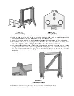
                Positioning the End Support 


                                 Raising Frame   


7.


After the end support rails are securely tightened, tighten the rail bolts on the fixed end (these bolts 
were left loose in step 4 above). 

8.


Using a forklift truck carefully stand the frame assembly upright, lifting it by the upper rail as 
shown in figure 6-6.  

9.


After the press is upright (see figure 6-7) and in the desired location it must be leveled so the plates 
and terminals will hang correctly.  Make sure the fixed end is plumb.  This can be accomplished 
by putting a spirit level across the ports (see figure 6-8).  Adjust the ball feet as necessary.  Caution: 
Do not exceed maximum port center height as shown in the drawing package.


Summary of Contents for Pro31-M

Page 1: ...AGC Model Pro31 M Operation and Maintenance Manual ...

Page 2: ......

Page 3: ...List 8 Spindle Nut Assembly 9 Pushtube Assembly 10 Follower Roller Assembly 11 Pro3 Terminal Components 12 Pro3 Plate and Frame Gaskets 13 Eastern Factory Western Factory 10129 Piper Lane 9109 SE 64th Avenue Bristow Virginia 20136 Portland Oregon 97206 Phone 703 257 1660 Phone 503 774 7342 Fax 703 330 7940 Fax 503 774 2550 800 825 8820 800 715 8820 www AGCHeatTransfer com Revised 08 27 13 ...

Page 4: ......

Page 5: ...ch AGC frame is assembled and fully tested at the factory prior to shipping After testing the unit is prepared for shipping When the press leaves the factory it is in perfect condition Upon arrival carefully inspect the frame for any damage that may have occurred during shipping If you notice any damage from shipping or otherwise note it on the shipping paperwork and report it to AGC immediately I...

Page 6: ...agram If this dimension is exceeded the leg could disengage from the socket and the frame could tip When moving the frame the top rail can provide a good lifting point However when using the top rail as a lifting point exercise caution to prevent damaging the plate hanger Do not attempt to lift a frame using the port nozzles as a lifting point Lifting a frame by the port nozzles could crack the no...

Page 7: ...ith that frame Figure 3 Streaming Diagram Sample To close the frame turn the spindle screws clockwise It is important when closing the press that each screw shares the load equally At no time should the screws be engaged at drastically different lengths This could cause damage to the plates or to the spindle screws When checking the heat exchanger closed dimension it is important to check in two l...

Page 8: ...tail and should only be attempted by qualified equipment installers or maintenance technicians The components are large and could cause serious injury or death if mishandled The procedure described here is the method used at the factory to assemble the press Your particular site requirements and limitations may require deviation from this description It is assumed that the persons installing this ...

Page 9: ...ashers and 4 each 1 lock washers Prior to installation apply a liberal amount of food grade anti seize to the threads of each bolt 4 Position the bottom rail as shown in figure 6 2 Loosely bolt the bottom rail in place It may be necessary to adjust the rail to install the end support 5 Position the upper rail as shown in figure 6 3 hanger side toward the bottom rail and loosely bolt the rail in pl...

Page 10: ... a forklift truck carefully stand the frame assembly upright lifting it by the upper rail as shown in figure 6 6 9 After the press is upright see figure 6 7 and in the desired location it must be leveled so the plates and terminals will hang correctly Make sure the fixed end is plumb This can be accomplished by putting a spirit level across the ports see figure 6 8 Adjust the ball feet as necessar...

Page 11: ...ary to remove the roller To remove the follower roller remove one of the snap rings on the roller pin then slide the pin out and remove the roller 13 The follower is installed using a lifting sling The follower is wrapped with the sling in a cinch configuration and tilted into position using a forklift truck figure 6 9 After the follower is over the bottom rail stand the follower upright and re in...

Page 12: ... HOT The press must be cooled below 90 F prior to opening Press Monthly Lube Inspection 1 Lockout Tagout the voltage supply to the press 2 Inspect the spindle shafts for signs of wear 3 Apply food grade grease to the exposed threads of the spindle shaft 4 Remove lockout tagout device and return press to service Parts List Replacement parts for the Model Pro31 M can be ordered from AGC or your loca...

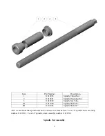
Page 13: ... Retaining Nut 3 11010902 Spindle Nut Tube 4A 11011000 Spindle Shaft 50 4B 11101001 Spindle Shaft 62 AGC recommends that spindle and nut be ordered as a matched set For a 50 spindle order assembly number 11010911 For a 62 spindle order assembly number 11010910 Spindle Nut Assembly ...

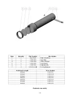
Page 14: ...Slip Disk 4 1 11011104 Thrust Washer 5 1 11011105 Lock Insert 6 1 11011106 Pushtube Pin 7 2 39 5133 50H E Clip Retainer Push Tube Length Part Number 10 Inch 11011111 14 Inch 11011110 18 Inch 11011112 24 Inch 11011115 28 Inch 11011117 32 inch 11011113 36 Inch 11011116 Pushtube Assembly ...

Page 15: ...rt Number Description 1 1 11016210 Follower Roller Pro31 2 2 SSR16 2RS Stainless Steel Ball Bearing 3 2 5100 100H Stainless Steel Snap Ring 4 1 11016212 Pro31 Follower Roller Pin Follower Roller Assembly AGC P N 11016213 ...

Page 16: ...500 Pro3 Terminal Roller with Pin 11015007 Pro3 Port Boss V Configuration with 3 connection 11018516 Pro3 Port Boss X Configuration with 3 connection 11018515 Pro3 Port Boss Thru with 2 connection 11018520 Pro3 Blank Port Boss 11018520 Pro3 Thru Boss 11018513 Pro3 Terminal Components ...

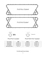
Page 17: ...et NBR EPDM VITON Flow Gasket AGPRO301N AGPRO301E AGPRO301V End Gasket AGPRO302N AGPRO302E AGPRO302V Port Gasket AGPRO303N AGPRO303E AGPRO303V FDA Port Gasket 11018572 11018578 11018583 Pro3 Plate and Frame Gaskets ...

Page 18: ......

Page 19: ...http agcheattransfer com ...

Reviews: