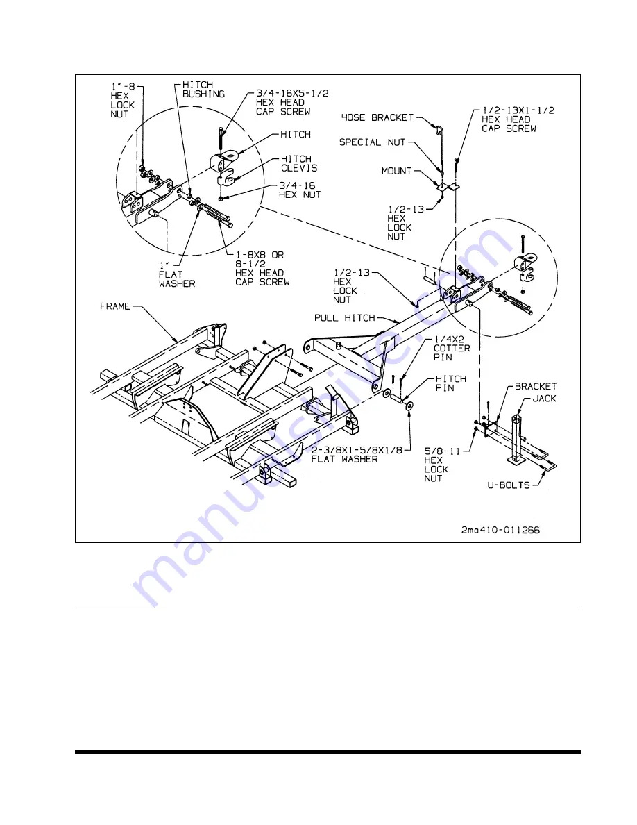
3-10 PULL HITCH INSTALLATION
IMPORTANT
SEE FIGURE 3-18 FOR PART NAMES.
3-10.1
Install pull hitch to frame using hitch
pins and cotter pins.
3-10.2
Assemble the hitch ring to the pull hitch
as shown with the recess down.
3-10.3
Install jack on pull hitch. Do not over-
tighten U-screws on jack. It will cause jack to
bind.
IMPORTANT
USE JACK MOUNTING TUBE ON RIGHT SIDE
OF PULL HITCH FOR CORRECT ANGLE ON
JACK.
3-10.4
Install hose bracket and hose bracket
mount on pull hitch with special nut, screw,
and lock nuts.
3-17
Figure 3-18 Pull Hitch Installation
Summary of Contents for Glencoe SF4800
Page 1: ...Glencoe MODEL SF4800 SOIL FINISHER OPERATOR S MANUAL Form No 79019152 March 2001...
Page 2: ......
Page 3: ...MODEL SF4800 SOIL FINISHER OPERATOR S MANUAL PURCHASED FROM DATE ADDRESS PHONE NO SERIAL NO...
Page 4: ......
Page 11: ...2 4 Figure 2 1 11 4 Shank Placement Assembly...
Page 12: ...2 5 Figure 2 2 14 0 Shank Placement Assembly...
Page 13: ...2 6 Figure 2 3 16 8 Shank Placement Assembly 1 of 2...
Page 14: ...2 7 Figure 2 4 16 8 Shank Placement Assembly 2 of 2...
Page 15: ...2 8 Figure 2 5 19 4 Shank Placement Assembly 1 of 2...
Page 16: ...2 9 Figure 2 6 19 4 Shank Placement Assembly 2 of 2...
Page 17: ...2 10 Figure 2 7 22 0 Shank Placement Assembly 1 of 2...
Page 18: ...2 11 Figure 2 8 22 0 Shank Placement Assembly 2 of 2...
Page 19: ...2 12 Figure 2 9 24 8 Shank Placement Assembly 1 of 2...
Page 20: ...2 13 Figure 2 10 24 8 Shank Placement Assembly 2 of 2...
Page 21: ...2 14 Figure 2 11 27 4 Shank Placement Assembly 1 of 2...
Page 22: ...2 15 Figure 2 12 27 4 Shank Placement Assembly 2 of 2...
Page 23: ...2 16 Figure 2 13 30 0 Shank Placement Assembly 1 of 2...
Page 24: ...2 17 Figure 2 14 30 0 Shank Placement Assembly 2 of 2...
Page 25: ...2 18 Figure 2 15 32 8 Narrow Frame Shank Placement Assembly 1 of 2...
Page 26: ...2 19 Figure 2 16 32 8 Narrow Frame Shank Placement Assembly 2 of 2...
Page 27: ...2 20 Figure 2 17 32 8 Wide Frame Shank Placement Assembly 1 of 2...
Page 28: ...2 21 Figure 2 18 32 8 Wide Frame Shank Placement Assembly 2 of 2...
Page 29: ...2 22 Figure 2 19 35 4 Shank Placement Assembly 1 of 2...
Page 30: ...2 23 Figure 2 20 35 4 Shank Placement Assembly 2 of 2...
Page 31: ...NOTES 2 24...
Page 33: ...3 2 Figure 3 1 Frame Assembly 30 to 35...
Page 35: ...3 4 Figure 3 2 Rockshaft Installation Frame Figure 3 3 Rockshaft Installation Frame 30 and 35...
Page 37: ...3 6 Figure 3 5 Wing and Wing Extensions 17 35 Models...
Page 40: ...3 9 Figure 3 9 Fold Cylinder Bracket 17 through 27...
Page 41: ...3 10 Figure 3 10 Fold Cylinder Bracket 30 and Larger...
Page 42: ...3 11 Figure 3 11 Installation of Fittings in Manifold...
Page 43: ...3 12 Figure 3 12 Installation of Shanks and Clamps...
Page 45: ...3 14 Figure 3 14 Spring Shank Assembly Figure 3 15 Ratchet Jack Installation...
Page 46: ...3 15 Figure 3 16 Disc Gang Hydraulic Assembly...
Page 49: ...3 18 Figure 3 19 Leveling Assembly Installation...
Page 51: ...3 20 Figure 3 20 Warning Light Installation...
Page 53: ...3 22 Figure 3 21 Hydraulic Radius Rod...
Page 54: ...3 23 Figure 3 22 Rear Hitch Assembly Option...
Page 57: ...NOTES 3 26...
Page 64: ...4 7 Figure 4 6 Spike Harrow 3 and 5 Bar Figure 4 7 Spike Harrow Tilloll Style...
Page 67: ...4 10 Figure 4 11 Lubrication Schedule...
Page 69: ...NOTES 4 12...
Page 72: ...NOTES 5 3...
Page 73: ......
Page 74: ......
Page 75: ...Glencoe AGCO CORPORATION 4205 River Green Parkway Duluth Georgia 30096 Printed in U S A...


