background image

P r e f a c e 

4

Preface


A b o u t  S n a p S c a n  E Z 


E n v i r o n m e n t a l  R e q u i r e m e n t s 


P r e c a u t i o n s 


C l e a n i n g  y o u r  S c a n n e r 


H o w  t o  U s e  t h i s  G u i d e 


H o w  t o  P r i n t  t h i s  O n l i n e  G u i d e 

Summary of Contents for Scanner

Page 1: ...r SnapScan EZ for installation Chapter 2 Installing the Scanner This chapter shows you how to set up your SnapScan EZ Appendix A Troubleshooting Troubleshooting can be helpful when you come across problems Appendix B Technical Information on the SnapScan EZ This appendix provides specifications for your SnapScan EZ Appendix C SnapScan EZ Regulation Compliance This appendix gives you information ab...

Page 2: ...s NT are trademarks or registered trademarks of Microsoft Corporation iPhoto Express and iPhotoPlus are trademarks of Ulead Other product or company names are trademarks or registered trademarks of their respective holders Copyright 1998 Agfa Gevaert N V All rights reserved All software and hardware described in this document are subject to change without any notice Conventions The following conve...

Page 3: ...nner Hardware 14 Connecting the Scanner 14 Testing the Scanner 17 Installing the Software 18 Windows 95 and Windows NT 4 0 18 Windows 3 11 and Windows NT 3 51 19 Placing Reflective Originals 21 A p p e n d ix A T ro u b le sh o o t in g 2 2 A p p e n d ix B T e ch n ical In f o rmat io n o n t h e S n ap S can E Z 2 5 A p p e n d ix C S n ap S can E Z R e g u lat io n C o mp lian ce 2 6 Safety Reg...

Page 4: ...Pref ac e 4 Preface About SnapScan EZ Environmental Requirements Precautions Cleaning your Scanner How to Use this Guide How to Print this Online Guide ...

Page 5: ...s The scanner driver software gives you a number of additional features to create special effects or to reproduce even the most difficult originals The document cover is adjustable when you put a thick original like a book or a magazine on the reflective glass plate the document cover adapts to the thickness of the original Environmental Requirements Place the scanner on a horizontal flat surface ...

Page 6: ... the scanner housing or the glass plate and when the scanner needs servicing or repairing Do not open the scanner housing as it contains high voltage areas and sensitive components Every repair should be carried out by your dealer Do not leave originals on the reflective glass plate for excessive periods of time The warmth of the scanner may cause them to deteriorate For safety reasons never use e...

Page 7: ...F o rward buttons to retrace your steps in this guide moving to each view in the order visited Use the P re vio u s P ag e or N e xt P ag e button to move the document backward or forward one page at a time You can also use the keyboard arrows Use the z o o m t o o l to magnify and reduce Control click the page display Click the F in d button to search for part of a word a complete word or multipl...

Page 8: ... Preparing t he Sc anner 8 Chapter 1 Preparing the Scanner This chapter helps you to prepare your SnapScan EZ for installation Unpacking the Scanner Unlocking the Scanner Locking the Scanner Taking a Closer Look ...

Page 9: ...terials to protect the scanner during later transport Unlocking the Scanner The scanner s optical box contains all optical components and rides back and forth during the scan A locking slider holds it in place during shipment Before you switch on the scanner you first have to unlock it 1 Place the scanner on a horizontal flat surface and pull it carefully towards you until you can see the locking ...

Page 10: ...rriage from possible damage 1 Place the scanner on a horizontal flat surface and pull it towards you until you can see the locking slider at the bottom 2 Switch on your scanner The scanner s optical assembly moves to its home position 3 When the status indicator stops blinking slide the locking slider to the left Your scanner is locked 4 Switch off your scanner ...

Page 11: ...have the scanner out of the box take a closer look so that you become familiar with its parts The figures illustrate the locations of the different parts of your SnapScan EZ 1 glass plate 2 adjustable document cover 3 rulers 4 power switch 5 power indicator status indicator ...

Page 12: ... 1 Preparing t he Sc anner 12 1 power connector 2 25 pin interface plug marked with a computer icon for connection to your PC 3 25 pin interface socket marked with a printer icon for connection to your printer ...

Page 13: ...his chapter shows you how to set up your SnapScan EZ Minimum Hardware Requirements Installation of the Scanner Hardware Connecting the Scanner Testing the Scanner Installing the Software Windows 95 and Windows NT 4 0 Windows 3 11 and Windows NT 3 51 Placing Reflective Originals ...

Page 14: ...ive The amount of disk space available on your PC determines the number and the size of the images that you can scan Make sure that you have enough free storage space on your hard disk You need about two times the size of the image to scan edit and save it Installation of the Scanner Hardware This section shows you how to set up your SnapScan EZ with your PC and your printer You can find instructi...

Page 15: ...el Interface cable into the printer port of your computer C a u t i o n Mak e s ure t o plug t he Parallel I nt erf ac e c able int o t he print er port and not int o any ot her res embling port I f damage c aus ed by wrong c onnec t ion oc c urs warrant y will be v oided ...

Page 16: ...r icon at the rear of the scanner Note Do not forget to secure the connection by tightening the connector screws 5 Connect the printer cable to the socket marked with a printer icon at the rear of the scanner Note Do not forget to secure the connection by tightening the connector screws 1 Parallel Interface cable 2 printer cable ...

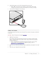
Page 17: ...y connected to your PC C a u t i o n Chec k if t he s c anner is properly unloc k ed 1 Switch on the scanner The scanner performs a self test during which the status indicator blinks slowly This takes about 15 seconds or less After the self test the status indicator remains on Note If a malfunction is detected during the self test that is if the status indicator starts blinking at a higher frequen...

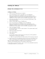
Page 18: ...f it does not run the program first double click the CD ROM icon in My Computer and then double click a g f a s c a n e x e 6 Click your language English You will be asked if you want to install Acrobat You need Acrobat to read your documentation 7 Select your scanner from the list 8 Click Install software 9 Click Register You can either register electronically or you can print out the registratio...

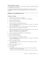
Page 19: ...ng Windows 3 11 follow the instructions on your screen and install iPhotoPlus the image editing software or If you are using Windows NT 3 51 follow the instructions on your screen and install iPhoto Express the image editing software 7 Remove the CD ROM from your CD ROM drive 8 Insert the Agfa Scanners CD ROM into your CD ROM drive 9 Open the Program Manager 10 From the File menu choose Run 11 Typ...

Page 20: ...r restarting your PC the scanner is ready for use For the latest up to date information refer to the FotoLook Read Me file and the FotoSnap Read Me file on your computer Installing Additional Software To install additional software insert the Software Collection II CD ROM and follow the instructions on your screen For a general overview of the additional software and for the location of the docume...

Page 21: ...he middle of the front ruler The optical performance of a CCD scanner is always best near the middle of the glass plate However the specified scan quality is guaranteed for the entire scan area If you put more than one original on the glass plate position them as close to the center line as possible to optimize quality 3 Lower the document cover of the scanner The adjustable document cover makes i...

Page 22: ...e scanner was not properly unlocked Immediately switch off the scanner and unlock it properly or contact your dealer or local Agfa support center The status indicator on the scanner s operating panel starts blinking at a higher frequency after the power up sequence 15 seconds A malfunction has been detected by the scanner Check if you have unlocked the scanner Switch off the scanner and switch it ...

Page 23: ...P mode If you cannot change the Parallel Port mode to one of these modes leave the settings untouched If you can choose between several of these modes always select the mode occurring first in the following row EPP EPP ECP or ECP In case of problems contact your PC dealer or your system administrator to change the settings Using your scanner with other parallel port devices If you encounter diffic...

Page 24: ...device or its driver is n o t compatible with the above mentioned protocol If you are using Windows 3 11 protocol not implemented In these two cases simultaneous operation of two or more devices on the printer port is very likely to cause severe problems scanning while printing scanning directly to a parallel port removable drive and so on may cause unexpected results Your PC has two printer ports...

Page 25: ... gray 30 bits for color S can n in g sp e e d line art 3 ms line gray 3 ms line color 8 ms line M aximu m scan n in g are a 8 5 x 11 7 inch L amp cold cathode P o we r o n t o re ad y t ime 15 seconds P o we r su p p ly voltage 100 V to 130 V frequency 57 Hz to 63 Hz D ime n sio n s length 17 5 inch width 13 inch height 4 3 inch weight ca 1 8 lb In t e rf ace parallel port 2 x 25 pin connector T r...

Page 26: ...Appendix C SnapSc an Regulat ion Complianc e 26 Appendix C SnapScan EZ Regulation Compliance Safety Regulations Electromagnetic Compatibility ...

Page 27: ...Beschädigung des Gerätes zu vermeiden sollten Sie nur Zuberhörteile verwenden die vom Hersteller zugelassen sind 3 Das Gerät ist vor Feuchtigkeit zu schützen 4 Bei der Aufstellung des Gerätes ist auf sicheren Stand zu achten Ein Kippen oder Fallen könnte Verletzungen hervorrufen Verwenden Sie nur sichere Standorte und beachten Sie die Aufstellhinweise des Herstellers 5 Die Belüftungsöffnungen dien...

Page 28: ...ce to radio communications However there is no guarantee that interference will not occur in a particular installation If this equipment does cause harmful interference to radio or television reception which can be determined by turning the equipment off and on the user is encouraged to try to correct the interference by one or more of the following measures Reorient or relocate the receiving ante...

Reviews: