background image

16

198935 R17

10. Make sure that an integral end-to-end connection exists between all mating uprights. Successive uprights

must not overlap.

11. Vertical tolerances between uprights and wall sheets are tight. This can be affected by “jacking” techniques,

which can allow the tolerance to grow or shrink depending on the technique used. The gapping between
successive uprights must be monitored to ensure that upright holes align with wall sheet holes.

12. If catwalks are being installed on the structure, upright catwalk upgrades are likely required. The upgraded

stiffeners must be installed in the correct locations to support the intended catwalk loads. Also, the
structure must be properly oriented to ensure the eventual correct alignment between the catwalks and the
supporting uprights. Finally, the connectors that tie into the uprights and support the catwalks are best
installed during assembly of the structure. See the catwalk assembly manual for additional details.

3.6. Product Storage

Rust on Galvanized Parts

1. White rust forms when moisture is allowed to collect on galvanized surfaces that have yet to develop the

durable zinc oxide layer. This zinc oxide layer naturally occurs as the surface interacts with carbon dioxide,
and is characterized over time by the dull grey appearance that weathered galvanized surfaces get.

2. Parts that are not well ventilated or well drained can collect water between surfaces and develop white rust.

3. White rust is not a structural concern if its development is stopped in the early stages. A light film or

powdery residue can occur after a period of heavy rainfall or a short time of improper storage. If white rust
has started to develop, separate parts and wipe off any moisture. Next, using a clean cloth, apply a thin
layer of petroleum jelly or food-grade oil to the entire part.

4. If moisture is left on parts, this white rust can become more aggressive and turn into red rust. Red rust can

cause degradation in the material and become a structural concern. Any parts that have red rust should be
replaced immediately.

Storage Guidelines

• Keep all bundles dry before assembly of the bin.

• Start assembly as soon as possible.

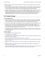
• Do not lay bundles on the bare ground. Raise all bundles 6" to 8" off the ground on wood blocks or timbers.

(See Detail A in

Figure 2 on page 17

.)

• Store curved wall sheets ‘hump-up’. (See Detail A in

Figure 2 on page 17

.)

• All other bundles material should be placed so they are well sloped to promote good drainage. (See Detail B

in

Figure 2 on page 17

.)

• Roof sheets must be elevated at least 12" at the small end of the sheets. (See Detail B in

Figure 2 on page

17

.)

• Temporary storage can be provided by erecting a simple framework supporting a waterproof tarp. (See

Detail C in

Figure 2 on page 17

.)

• All bin boxes, ladder boxes and hardware boxes should be stored inside. These are not waterproof, and will

deteriorate in normal weather conditions, allowing moisture to contact the parts inside.

3. BEFORE YOU BEGIN

HOPPER LADDER MAKE-UP PACKAGES – WIDE-CORR® GRAIN BIN

Summary of Contents for Westeel Wide-Corr

Page 1: ...ference Part Number 198935 R17 Revised February 2022 Original Instructions Hopper Ladder Make Up Packages Wide Corr Grain Bin Installation and Storage Instructions Part Number 198925 Revision 20 Revis...

Page 2: ...n this Manual The following changes have been made in this revision of the manual Description Section Updated vertical support ladder details Section 6 2 Optional Vertical Support Ladder Details on pa...

Page 3: ...ipment 19 4 3 Order Optional Equipment 19 5 Assembly 20 5 1 Assembly Safety 20 5 2 Ladder System Safety Requirements 21 5 3 Welded Hopper Ladder Make Up Packages 22 5 3 1 Welded Hopper Make Up Package...

Page 4: ...HOPPER LADDER MAKE UP PACKAGES WIDE CORR GRAIN BIN 4 198935 R17 6 2 Optional Vertical Support Ladder Details 39 6 3 Ladder Parts Identification 41 7 Limited Warranty Westeel Grain Bin Products 42...
Page 5: ...this Westeel Hopper Ladder Make Up Packages Everyone present at the assembly site is required to be familiar with all safety precautions Keep this manual available for frequent reference and review it...

Page 6: ...if not avoided may result in property damage 2 2 General Safety Information Read and understand all safety instructions safety decals and manuals and follow them when assembling the equipment Only ex...

Page 7: ...ome illegible See decal location figures that follow Replaced parts must display the same decal s as the original part Replacement safety decals are available free of charge from your distributor deal...

Page 8: ...that follow Safe operation and use of the hopper ladder requires that you familiarize yourself with the various safety decals and the areas or particular functions that the decals apply to as well as...

Page 9: ...Shut off and lock out all power 2 Use a lifeline safety harness and have an observer outside before entering the bin 3 Wear proper breathing equipment or a respirator 4 Avoid the center of the bin Fai...

Page 10: ...0 00228 When equipped with aeration system to prevent roof and or bin damage Use a minimum 1 square foot 0 1m2 opening for each 1000ft3 min 30m3 min of air Ensure all roof vents are open and unobstruc...

Page 11: ...rades are available Table 1 Peak Loads for Various Roofs Size Type of Roof Load lbs Load kg 15 to 24 non structural 4000 lbs 1814 kg 27 to 48 non structural 5000 lbs 2268 kg 51 54 non structural 8000...

Page 12: ...1 39 18 29 1 39 21 24 1 15 40 1 92 24 17 0 81 27 1 29 27 10000 44 5 19 0 91 28 1 34 30 15 0 72 24 1 15 33 1 58 33 18 0 86 24 1 15 36 1 72 36 18 0 86 23 1 10 31 1 48 39 16 0 77 21 1 01 30 1 44 42 14 0...

Page 13: ...96 37 1 77 102 32 1 53 105 32 1 53 108 32 1 53 Table 5 Maximum Roof Snow Load at UPGRADED Peak Loads Bin Series Upgraded Peak Load Standard Roof lbs kN psf kPa 48 60000 266 9 38 1 82 51 38 1 82 54 38...

Page 14: ...nditions Westeel will not assume any liability for results arising from their use Important Foundation should be uniform and level Level should not vary by more than over a span of four feet under the...

Page 15: ...ring of a non stiffened bin or tank and b shimming under the uprights of a stiffened bin or tank or under the legs of a hopper 4 Make sure that the proper hardware is utilized for all bolted connectio...

Page 16: ...tween surfaces and develop white rust 3 White rust is not a structural concern if its development is stopped in the early stages A light film or powdery residue can occur after a period of heavy rainf...

Page 17: ...parts inside If Parts Become Wet 1 If goods become submerged or wet the bundles should be opened as soon as possible sheets or material separated and dried Keep separated until assembly Brace goods p...

Page 18: ...oaded from the center Contact local power officials for minimum power line clearance See Section 3 5 Critical Assembly Requirements on page 15 for mandatory siting and assembly requirements Store only...

Page 19: ...arge pocket carpenter pouch 8 20 cm metal punches for aligning bolt holes Step and extension ladders construction grade 6 point wrenches Imperial box end Metal cutting saw suitable for cutting roof ri...

Page 20: ...el surface Always have two or more people assembling the hopper ladder Make sure you have sufficient lighting for the work area Tighten all fasteners according to their specifications Do not replace o...

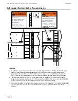
Page 21: ...ortant Regulations require that fixed ladders over a certain height must be outfitted with platforms and cages or other approved fall arresting devices For information on the specific requirements app...

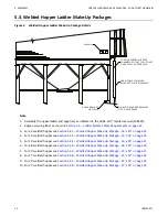
Page 22: ...5 3 1 Welded Hopper Make Up Package 14 x 35 on page 23 4 For 15 welded hopper see Section 5 3 2 Welded Hopper Make Up Package 15 x 35 on page 24 5 For 16 welded hopper see Section 5 3 3 Welded Hopper...

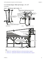
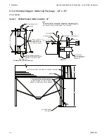
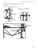
Page 23: ...R TO THE SUPPORT CHANNELS SECTION A A BOTTOM CAGE HOOP P N 234162 BLOT TO SC LADDER CLIP LADDER LADDER SUPPORT CHANNEL WALL SHEET HOPPER RING BEAM 3 8 x 1 BOLT A A NOTE HOLES ON THE TOP OF SUPPORT CHA...

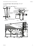
Page 24: ...SHEET HOPPER RING BEAM 3 8 x 1 BOLT A A NOTE HOLES ON THE TOP OF SUPPORT CHANNELS ALIGN BOLT WITH MATING HOLES ON THE LADDER SEGMENT HOPPER RING BEAM NO LADDER CLIPS ARE REQUIRED AT THIS LOCATION DET...

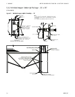
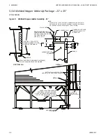
Page 25: ...P N 234162 LADDER WALL SHEET HOPPER RING BEAM 3 8 x 1 BOLT A A NOTE HOLES ON THE TOP OF SUPPORT CHANNELS ALIGN BOLT WITH MATING HOLES ON THE LADDER SEGMENT HOPPER RING BEAM NO LADDER CLIPS ARE REQUIRE...

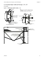
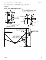
Page 26: ...162 BOLT TO SUPPORT CHANNELS LADDER LADDER SUPPORT CHANNEL WALL SHEET HOPPER RING BEAM 3 8 x 1 BOLT A A NOTE HOLES ON THE TOP OF SUPPORT CHANNELS ALIGN BOLT WITH MATING HOLES ON THE LADDER SEGMENT HOP...

Page 27: ...SUPPORT CHANNELS P N 234491 SO THAT FLANGES POINT OUTWARDS USE 3 8 x 1 BOLTS TO SECURE LADDER TO THE SUPPORT CHANNELS SECTION A A STANDARD CAGE HOOP P N 234161 BLOT TO SC LADDER CLIP LADDER LADDER SU...

Page 28: ...DDER INSTALL SUPPORT CHANNELS P N 234492 SO THAT FLANGES POINT OUTWARDS USE 3 8 x 1 BOLTS TO SECURE LADDER TO THE SUPPORT CHANNELS SECTION A A LADDER LADDER SUPPORT CHANNEL 4 0 WC LADDER CLIP STANDARD...

Page 29: ...34161 LADDER WALL SHEET HOPPER RING BEAM 3 8 x 1 BOLT A A NOTE HOLES ON THE TOP OF SUPPORT CHANNELS ALIGN BOLT WITH MATING HOLES ON THE LADDER SEGMENT HOPPER RING BEAM NO LADDER CLIPS ARE REQUIRED AT...

Page 30: ...4161 LADDER WALL SHEET HOPPER RING BEAM 3 8 x 1 BOLT A A NOTE HOLES ON THE TOP OF SUPPORT CHANNELS ALIGN BOLT WITH MATING HOLES ON THE LADDER SEGMENT HOPPER RING BEAM NO LADDER CLIPS ARE REQUIRED AT T...

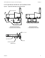
Page 31: ...ion Details Page B5 SECTION A4 ANGLE BRACKET ATTACHMENT FOUNDATION DETAILS LADDER 3 8 x 1 BOLT SUPPORT CHANNEL ANGLE BRACKET ANGLE BRACKET CONCRETE PAD OPTION WITH ANCHOR BOLTS NOT INCLUDED B B STEEL...

Page 32: ...Note 2 Note 1 Assemble the upper ladder and cage tiers as indicated in the Wide Corr ladder manual 198925 2 Apply a warning label as shown in Section 5 2 Ladder System Safety Requirements on page 21 3...

Page 33: ...ADDER INSTALL SUPPORT CHANNELS P N 234526 SO THAT FLANGES POINT OUTWARDS USE 3 8 x 1 BOLTS TO SECURE LADDER TO THE SUPPORT CHANNELS SECTION A A LADDER LADDER SUPPORT CHANNEL 4 0 WC LADDER CLIP STANDAR...

Page 34: ...N 234161 LADDER WALL SHEET HOPPER RING BEAM 3 8 x 1 BOLT A A NOTE HOLES ON THE TOP OF SUPPORT CHANNELS ALIGN BOLT WITH MATING HOLES ON THE LADDER SEGMENT HOPPER RING BEAM NO LADDER CLIPS ARE REQUIRED...

Page 35: ...OF SUPPORT CHANNELS ALIGN BOLT WITH MATING HOLES ON THE LADDER SEGMENT HOPPER RING BEAM NO LADDER CLIPS ARE REQUIRED AT THIS LOCATION DETAIL 1 ANGLE BRACKET P N 234522 19 3 FOR 21 13 8 FOR 24 HOLES IN...

Page 36: ...LADDER WALL SHEET HOPPER RING BEAM 3 8 x 1 BOLT A A NOTE HOLES ON THE TOP OF SUPPORT CHANNELS ALIGN BOLT WITH MATING HOLES ON THE LADDER SEGMENT HOPPER RING BEAM NO LADDER CLIPS ARE REQUIRED AT THIS...

Page 37: ...ation Details Page C5 SECTION B4 ANGLE BRACKET ATTACHMENT FOUNDATION DETAILS LADDER 3 8 x 1 BOLT SUPPORT CHANNEL ANGLE BRACKET ANGLE BRACKET CONCRETE PAD OPTION WITH ANCHOR BOLTS NOT INCLUDED B B STEE...

Page 38: ...2 1 234484 24 x 35 4 4 1 1 2 1 234485 27 x 35 4 4 2 2 1 234536 15 x 45 4 4 1 1 2 1 234537 18 x 45 4 4 1 1 2 1 234538 21 x 45 24 x 40 4 4 2 2 1 234486 27 x 40 5 6 1 1 1 2 1 Table 7 Wide Corr Hopper La...

Page 39: ...s or Less Hopper Size of Legs Hopper Ht ft Rows of Supports Needed For Ladder Configuration Needed For Span Between 2 Legs Stiffened SSK 15 Dia 10 9 2 3 3 1 18 Dia 12 10 6 3 3 1 21 Dia 14 12 1 4 4 1 W...

Page 40: ...rews 3 8 dia min for spans greater than 60 Please see Wide Corr Ladder Installation Manual 198925 for further installation details of vertical ladders For every one of 234568 or 234569 purchased you w...

Page 41: ...dder to Wall Clip 234504 Ladder Support Arm 1 Dia x 34 3 4 Long 234505 Ladder Pass Thru Rail 234514 16 Ladder Cage Support 234517 Ladder Support Arm Clip 234518 Ladder Support Arm Bracket 234519 Inter...

Page 42: ...months Structural 30 months Elite Cones Paint 30 months Structural 10 years WESTEEL cones Paint No Warranty Structural 12 months Smooth Wall Bins Paint 60 months Structural 10 years Commercial Smooth...

Page 43: ...mers Limitations as to Manufacturer The warranty does not cover products sold by Westeel that are not manufactured by Westeel In those circumstances the purchaser is referred to the manufacturer of th...

Page 44: ...forceable in whole or in part such provision shall be deemed severable and will not affect or impair the legal validity of any other provision of the warranty 7 LIMITED WARRANTY WESTEEL GRAIN BIN PROD...
Page 45: ...198935 R17 45 HOPPER LADDER MAKE UP PACKAGES WIDE CORR GRAIN BIN 7 LIMITED WARRANTY WESTEEL GRAIN BIN PRODUCTS...
Page 46: ...ertilizer grain and feed systems with a growing platform in providing equipment and solutions for food processing facilities AGI has manufacturing facilities in Canada the United States the United Kin...

Reviews: