JR6: Mechanical Setting
Initial tests
Before any interfering with mechanical setting of JR6 try to perform
several quick tests. Install holder with problematic sample, close the
coils and install shielding hat. Then switch ON the spinner and run the
JR6SERV.exe software.
Test 1
• Switch on high speed using command “
h
” and run the measure-
ment with command “
g
”.
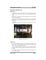
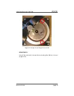
• Slightly move bottom trapezoidal plate, marked by the red arrow
in Fig.
, during the rotation of the sample. Move the plate to right,
left, back and forward,
not up or down
.
• If you will notice decrease or disappearing of the vibrations, then
try to adjust position of cardan shaft according to
Adjustment 1
.
• If there will not be any improvement during this first test do not
try to adjust the cardan axis.
• Try to perform same operation for low speed. Use command “
l
”
(small L) for set low speed and do the same things as for high
speed.
Test 2
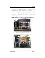
• Check the integrity of two damping foams placed above and be-
tween bronze plates, marked by two arrows in Fig.
• Press bronze plates together few times and check flexibility of the
damping pads. Primarily the lower one, marked by green arrow in
Fig.
, must be flexible, in good order and in correct distance.
• If the damping pads seems to be disintegrated, ask Agico for fur-
ther assistance.
• Switch on high speed using command “
h
” and run the measure-
ment with command “
g
”.
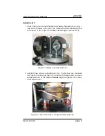
• During the rotation of the sample try to slightly change the dis-
tance between two round plates shown in Fig
. by pressing them
or lifting them by hand.
• If you will notice some improvement try to adjust the distance be-
tween two round plates according to the
Adjustment 2
.
• If there will not be any improvement during this test do not try to
adjust distance of the plates.
Service note
page 2


