JR6: Mechanical Setting
Mechanical setting of JR6
Adjustment 1
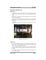
• In ideal situation, axis of the cardan shaft is coaxial with the sample
holder. Correct alignment of cardan shaft is marked by green line
in Fig.
• Sometimes a small non-coaxiality is better, because it can remove
vibration of mechanics.
• Adjustment can be done by the loosing two screws, marked by the
blue circle in Fig.
, adjusting of the cardan position and tightening
the screws.
• It is better to dismantle driving belt when you perform such ad-
justment.
Figure 4: Cardan shaft
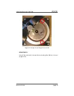
Adjustment 2
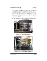
• This procedure describes how to adjust distance between round
plates. For first step, locate three nuts on upper round plate (red
arrow in Fig.
) and loose them a little.
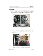
• Turn with three screws (red circle in Fig.
) to set correct distance
between two round plates. Note that only one of three screws is
marked.
• Small pliers must be used to turn three screws. Usually quarter of
turn is good enough.
Service note
page 4


