JR6: Mechanical Setting
Adjustment 3
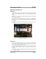
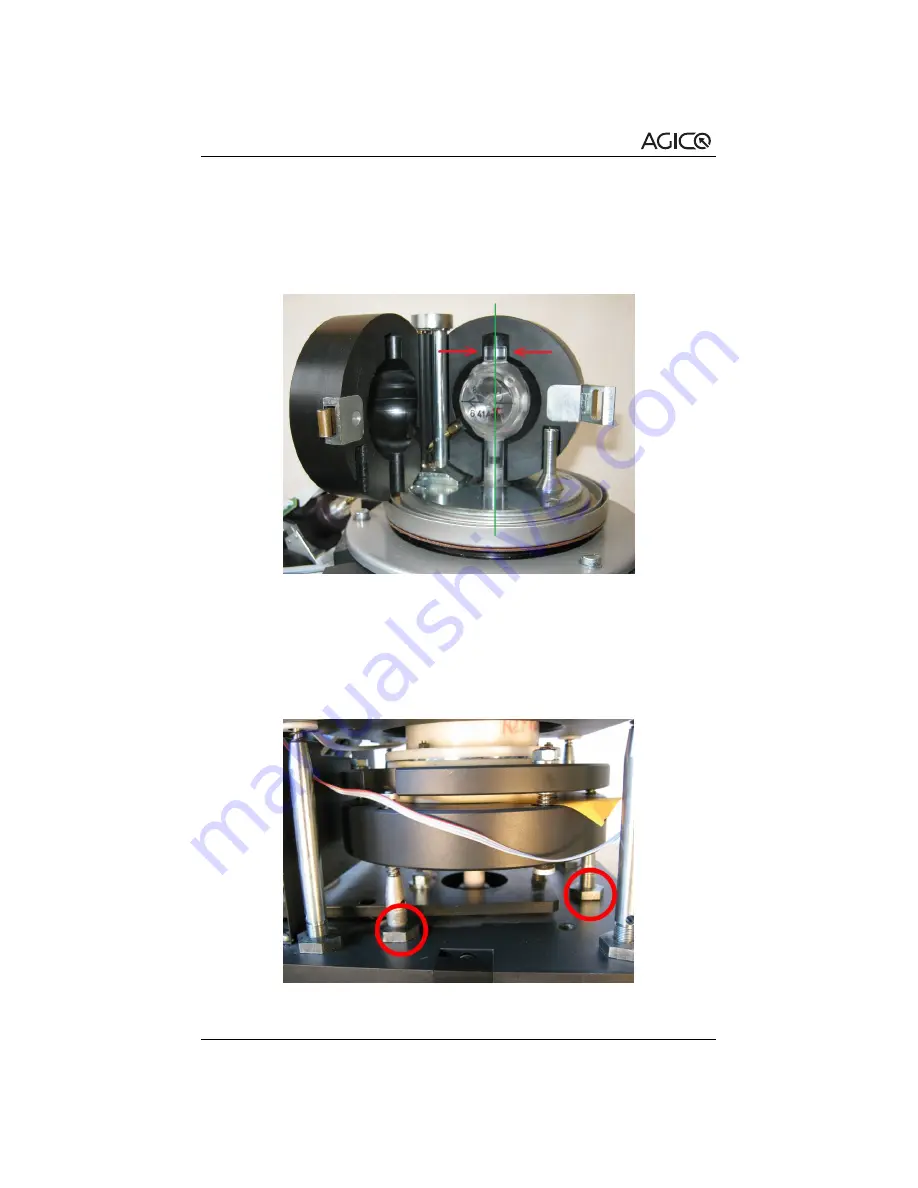
1. Check the axis of sample holder marked by the green line in Fig.
.
Top part of holder must be in the middle of space marked by the
red arrows. If not, adjust the holder according to the next step.
Figure 7: Holder in correct position
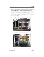
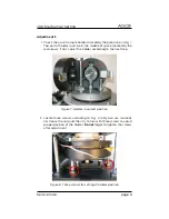
2. Locate three screws according to Fig.
(only two are marked).
First loose the nuts and then try to turn with three screws to adjust
proper position of the holder.
Do not
forget to tighten the screws
after adjustment.
Figure 8: Three screws for setting of holder position
Service note
page 6


