Pattern Markers
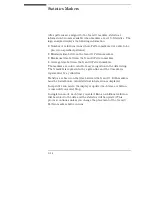
When Pattern markers are selected, two markers labeled X and O
become available. Pattern markers identify and mark unique bit
patterns in the display. Once the unique bit patterns are specified,
they can be used as reference points or as criteria for a stop
measurement. Even when you move the markers using one of the
other modes, the Pattern markers are not changed.
The markers are color coded for easy recognition in the display. The
X marker is represented by a green line and the O marker is
represented by a yellow line.
When a marker is positioned or moved in the Listing, Chart, or
Waveform menus, it is also positioned or moved in the other menus.
See Also
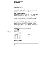
The "Specify Patterns Field" found later in this chapter for more
information on creating a pattern for the X and O markers.
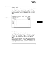
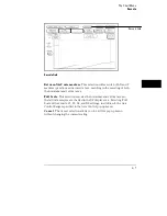
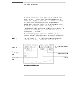
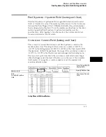
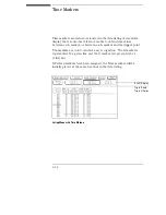
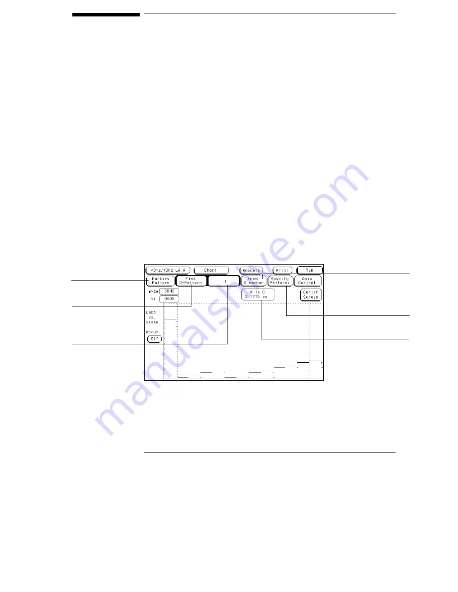
Chart Menu with Pattern Markers
Markers field
Find
X-pattern/O-pattern
field
From Trigger/Start/X Marker
field
Occurrence Counter
field
Specify Patterns field
X to O display
9–4
Summary of Contents for 16517A
Page 3: ...The Agilent Technologies 16517A 4 GSa S Timing and 1 GSa S State Logic Analyzer ii ...
Page 5: ...iv ...
Page 11: ...Contents 6 ...
Page 12: ...1 General Information ...
Page 18: ...2 Probing ...
Page 29: ...2 12 ...
Page 30: ...3 The Format Menu ...
Page 42: ...4 The Trigger Menu ...
Page 79: ...4 38 ...
Page 80: ...5 The Listing Menu ...
Page 86: ...6 The Waveform Menu ...
Page 106: ...7 The Compare Menu ...
Page 122: ...8 The Chart Menu ...
Page 133: ...8 12 ...
Page 134: ...9 Markers and Stop Measurements ...
Page 149: ...9 16 ...
Page 150: ...10 Skew Adjust ...
Page 156: ...11 Error Messages ...
Page 165: ...11 10 ...
Page 166: ...12 Specifications and Characteristics ...
Page 176: ...13 Installation and Service ...
Page 189: ...13 14 ...
Page 193: ...Index 4 ...

