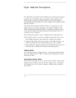
Not only can you sample at the external clock transitions, but you can
set the analyzer to oversample, in powers of two, up to 32x, or, up to a
maximum of 2 GHz sample rate. Each point of oversampling is
precisely distributed evenly within the external clock period.
Triggering
Defining a trigger specification is as easy as picking a predefined
macro from a trigger macro library. Trigger macros can be used by
themselves or in combination with each other. Resource terms
include four global patterns, two global edges, and one level
dependent timer/counter. By using trigger macros, or defining your
own trigger specification, the user-friendly and flexible triggering
architecture lets you create a large array of trigger sequencing or
qualification needed.
Acquisition Control
Data storage can begin at either the start, center, end, or a
user-defined point within memory. In addition, if the data of interest
occurs a relatively long time after trigger, you can delay storage after a
trigger by a user-defined amount. With all the acquisition control
available, you can fill acquisition memory very efficiently.
Measurement Display
Measurement data is displayed as waveforms or state data listings.
State data can be compared bit by bit to a user-defined reference
image. In the state listing, you can choose to display either sample
clock transitions or both sample clock and oversampling clock
transitions. In the timing waveform display, you can show state values
integrated in the waveform.
General Information
1–3
Summary of Contents for 16517A
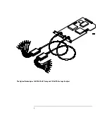
Page 3: ...The Agilent Technologies 16517A 4 GSa S Timing and 1 GSa S State Logic Analyzer ii ...
Page 5: ...iv ...
Page 11: ...Contents 6 ...
Page 12: ...1 General Information ...
Page 18: ...2 Probing ...
Page 29: ...2 12 ...
Page 30: ...3 The Format Menu ...
Page 42: ...4 The Trigger Menu ...
Page 79: ...4 38 ...
Page 80: ...5 The Listing Menu ...
Page 86: ...6 The Waveform Menu ...
Page 106: ...7 The Compare Menu ...
Page 122: ...8 The Chart Menu ...
Page 133: ...8 12 ...
Page 134: ...9 Markers and Stop Measurements ...
Page 149: ...9 16 ...
Page 150: ...10 Skew Adjust ...
Page 156: ...11 Error Messages ...
Page 165: ...11 10 ...
Page 166: ...12 Specifications and Characteristics ...
Page 176: ...13 Installation and Service ...
Page 189: ...13 14 ...
Page 193: ...Index 4 ...


