To Adjust the Channel-to-Channel Skew
Table 10-1
Equipment Required
Equipment
Critical Specification
Recommended Agilent
Model/Part
Qty
Calibration Module
No Substitutes
16517-63201
1
BNC Coax Cable
10503A
1
Connect the Logic Analyzer
1
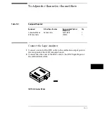
Connect one end of the BNC cable to the calibration output port on
the rear panel of the 16517A master board.
2
Connect the other end of the BNC cable to the BNC Signal Input of
the calibration module.
16517A Calibration Module
10–3
Summary of Contents for 16517A
Page 3: ...The Agilent Technologies 16517A 4 GSa S Timing and 1 GSa S State Logic Analyzer ii ...
Page 5: ...iv ...
Page 11: ...Contents 6 ...
Page 12: ...1 General Information ...
Page 18: ...2 Probing ...
Page 29: ...2 12 ...
Page 30: ...3 The Format Menu ...
Page 42: ...4 The Trigger Menu ...
Page 79: ...4 38 ...
Page 80: ...5 The Listing Menu ...
Page 86: ...6 The Waveform Menu ...
Page 106: ...7 The Compare Menu ...
Page 122: ...8 The Chart Menu ...
Page 133: ...8 12 ...
Page 134: ...9 Markers and Stop Measurements ...
Page 149: ...9 16 ...
Page 150: ...10 Skew Adjust ...
Page 156: ...11 Error Messages ...
Page 165: ...11 10 ...
Page 166: ...12 Specifications and Characteristics ...
Page 176: ...13 Installation and Service ...
Page 189: ...13 14 ...
Page 193: ...Index 4 ...

