background image

Specifications and Characteristics

This chapter lists the specifications and characteristics.
Specifications are the performance standards against which the
product is tested.

Characteristics are not specifications, but are included as additional
information.

For complete information on the test procedures to verify product
performance, refer to the optional 

Agilent Technologies 16517A/18A

Service Guide

, available from your Agilent Technologies Sales Office.

For instructions on running the self-tests, see the "Installation and
Service" chapter in this reference.

12–2

Summary of Contents for 16517A

Page 1: ... underutilized and idle equipment along with credit for buybacks and trade ins Custom engineering so your equipment works exactly as you specify Critical and expedited services Leasing Rentals Demos In stock Ready to ship TAR certified secure asset solutions Expert team I Trust guarantee I 100 satisfaction All trademarks brand names and brands appearing herein are the property of their respective ...

Page 2: ...uary 2000 For Safety information Warranties and Regulatory information see the pages behind the Index Copyright Agilent Technologies 1987 2000 All Rights Reserved Agilent Technologies 16517A 18A 4 GSa s Timing and 1 GSa s Synchronous State Logic Analyzer ...

Page 3: ...The Agilent Technologies 16517A 4 GSa S Timing and 1 GSa S State Logic Analyzer ii ...

Page 4: ... timing analyzer Some menus in the analyzer will change depending on the acquisition mode used For example because a timing analyzer does not use external clocks the external clock assignment fields in the Format menu will not be available If a menu field is only available to a particular acquisition mode the field is designated Timing only or State only after the field name If no designation is s...

Page 5: ...iv ...

Page 6: ...ns 2 9 Orientation Between Probe Tip and Interface 2 10 3 The Format Menu Synchronous State Acquisition Mode 3 3 Conventional Timing Acquisition Mode 3 4 Select Clock Field State Only 3 5 Set Sample Offset Field State Only 3 6 Pod Threshold Field 3 8 Label Polarity Fields 3 9 Bit Assignment Fields 3 10 Activity Indicators 3 12 Symbols Field 3 12 4 The Trigger Menu Trigger Sequence Levels 4 4 Modif...

Page 7: ...riod Field Timing only 4 34 Samples Clock Field State only 4 34 Armed By Field 4 37 5 The Listing Menu Markers Field 5 3 Data Roll Field 5 3 Label and Base Fields 5 4 Show States All Ext Clock State only 5 5 Sample Offset Field State only 5 6 Specify Patterns Field 5 6 Acquisition Control Field 5 6 6 The Waveform Menu Acquisition Control Field 6 3 Accumulate Field 6 4 Seconds Per Division Field 6 ...

Page 8: ...et Field State only 6 20 Reset Statistics Field 6 20 7 The Compare Menu Reference Listing Field 7 4 Difference Listing Field 7 5 Copy Listing to Reference Field 7 7 Find Error Field 7 8 Compare Full Compare Partial Field 7 9 Mask Field 7 10 Specify Stop Measurement Field 7 11 Data Roll Field 7 14 Bit Editing Field 7 15 Label and Base Fields 7 16 8 The Chart Menu The Y Markers 8 4 Markers Field 8 5...

Page 9: ...rm and Chart 9 7 Specify Patterns Field 9 8 Stop Measurement Field 9 10 Clear Pattern Field 9 11 Time Markers 9 12 Trig to X Trig to O Fields 9 13 Marker Label Base and Display Waveform menu 9 13 Statistics Markers 9 14 Reset Statistics Field Waveform menu 9 15 Clear Statistics Field Chart menu 9 15 10 Skew Adjust To Calibrate the Data Acquisition Module 10 2 To Adjust the Channel to Channel Skew ...

Page 10: ...ice To Inspect the Module 13 3 To Prepare the Mainframe 13 3 To Configure a One card Module 13 5 To Configure a Multi card Module 13 5 To Install the Module 13 7 To Test the Module 13 8 To Perform the Self tests 13 9 Access the Self tests 13 9 Perform the Functional Tests 13 10 Perform the Skew Adjustments and Tests 13 11 Exit the Self tests 13 12 To Return Assemblies 13 13 To Clean the Logic Anal...

Page 11: ...Contents 6 ...

Page 12: ...1 General Information ...

Page 13: ...er can be configured in the following ways The 16517A master can run as a single card module or have up to four 16518A expansion cards added for a multi card module Channel width varies from 16 channels on the 16517A master up to 80 channels when four 16518A expansion cards are added Channel memory depth is 64 Kbytes in both full channel state and timing modes or 128 Kbytes in half channel timing ...

Page 14: ...triggering architecture lets you create a large array of trigger sequencing or qualification needed Acquisition Control Data storage can begin at either the start center end or a user defined point within memory In addition if the data of interest occurs a relatively long time after trigger you can delay storage after a trigger by a user defined amount With all the acquisition control available yo...

Page 15: ...the screen over any dark blue box on the display with your finger until the field changes color Then remove your finger from the screen to activate your selection The area under your finger when you remove it from the screen is the area selected To activate a field with the mouse position the cursor of the mouse over the desired field and press the left button of the mouse The keyboard can control...

Page 16: ... 1 Conventional Timing Modes One Card Module Two Card Module Three Card Module Four Card Module Five Card Module Full Channel 16 channels 64 Kbits Deep 32 channels 64 Kbits Deep 48 channels 64 Kbits Deep 64 channels 64 Kbits Deep 80 channels 64 Kbits Deep Half Channel 8 channels 128 Kbits Deep 16 channels 128 Kbits Deep 24 channels 128 Kbits Deep 32 channels 128 Kbits Deep 40 channels 128 Kbits De...

Page 17: ...Logic Analyzers Table 1 3 Accessories Supplied Accessory Quantity Probe Pod 2 Probe Accessory Kit 1 Cable Assembly 1 Operating system disks 1 User s Reference 1 Accessories Available There are a number of accessories available that will make your measurement tasks easier and more accurate You will find these listed in Accessories for Agilent Logic Analyzers available from your Agilent Technologies...

Page 18: ...2 Probing ...

Page 19: ...2445A User Definable Interface optional Microprocessor and bus specific interfaces optional General Purpose Probing General purpose probing involves connecting the logic analyzer probes directly to your target system without using any interface General purpose probing does not limit you to specific hook up schemes as for example the probe interface does General purpose probing uses grabbers that c...

Page 20: ...e analyzer requires a clear connection with no termination Microprocessors are supported by universal interfaces or preprocessor interfaces or in some cases both There are a number of microprocessor and bus specific interfaces available as optional accessories listed in Accessories for Agilent Logic Analyzers Universal interfaces are aimed at initial hardware turn on and will provide fast reliable...

Page 21: ...nected to the assorted probing accessories at the signal end The pod housing contains termination networks and comparators that drive open collector outputs through the main cables In addition located on the pod housing is an equivalent circuit illustration showing pod loading and channel indicators for the 4 GHz operation All probe accessories connect to 0 1 inch centers Analyzer Probing System L...

Page 22: ...d 6 foot long contain eighteen 50 Ω transmission lines and 6 standard wires for assorted dc functions Channels Total of 17 channels Pod 1 is the LSB least significant byte and has 8 data channels and 1 external clock channel Pod 2 the MSB most significant byte has 8 data channels 16518A Expansion Card Cables Shielded 5 ft long contains eighteen 50 Ω transmission lines and 6 standard wires for asso...

Page 23: ... in diameter round pins Ground Leads The following probing components connect the system to ground Right Angle Ground Lead This flexible lead is one and a half inches long with a 90 degree bend off the lead tip It stacks on 0 1 inch centers Ground Extender If the circuit can tolerate an additional 0 5 to 1 pF capacitance this socket allows stacking on 0 1 inch centers Ground Connector This connect...

Page 24: ... surface mount components PGAs or cramped areas this wire can be tacked onto an IC lead for direct connection Grabbers These 0 05 pitch grabbers attach to adjacent IC pins with lead spacing greater than or equal to 0 50 in Probe pin kit 16517 82107 Qty 4 Grabber kit 16517 82108 Qty 20 SMT lead kit 16517 82104 Qty 4 red 4 black Probing Probing Accessories 2 7 ...

Page 25: ...ilable from your Agilent Technologies Sales Office Information on adjusting skew is also available in chapter 10 Skew Adjust BNC to SMB Cable Adapter On the back of the 16517A master card there are two SMB connectors used for external ECL arm in out signals Use this adapter between the BNC cable and the analyzer The adapter cable is only included in the Accessory Kit for the master card Calibratio...

Page 26: ...tip connects directly to the target system without any additional lead length added to the ground Depending on your measurement the added inductance caused by additional lead length may or may not cause a problem for the signal rise time of the target system However try to use the full performance configurations shown below when possible If you must add length to the ground lead use the following ...

Page 27: ...the probing system into the Format menu use the following points of identification 1 Use the color coded probe tips to identify the data channel or clock channel 2 Press the Pod ID button to display the pod number on screen When the Pod ID button is pressed an advisory is displayed in all menus identifying the pod number Probing Orientation Between Probe Tip and Interface 2 10 ...

Page 28: ...nterface by the assignment of a asterisk in the Bit Assignment field Other Helpful Hints Use labels with meaningful names to group data within the Format menu When new pods are added to the module they are added to the pod list in the Format menu In addition if there are more pods configured than can be displayed onscreen use the Pods roll field to roll unseen pods back onscreen Activity indicator...

Page 29: ...2 12 ...

Page 30: ...3 The Format Menu ...

Page 31: ... acquisition mode which in turn sets the clock source internal or external memory depth and maximum sampling speed Individual pod clock and data threshold levels are also set in the Format menu If the acquisition mode is set to operate as synchronous state other fields appear which set the external clock edge and the sample clock offset The sample clock offset allows the offset of the internal sam...

Page 32: ... used the channel width memory depth and maximum sampling speed State Mode Full Channel 1 GHz In State Mode Full Channel 1 GHz both pods are available on all configured cards Memory depth is 64 Kbits per channel State Acquisition Mode Selection Acquisition mode field State acquisition mode selection The Format Menu Synchronous State Acquisition Mode 3 3 ...

Page 33: ...de is up to 2 GHz Timing Mode Half Channel 4 GHz In Timing Mode Half Channel 4 GHz only bits 0 through 3 on all pods are available However memory depth is 128 Kbits per channel Sampling speed in this mode is fixed at 4 GHz When you switch back from the half channel mode you are asked if you want to restore bits 4 through 7 If you answer Yes you restore these bits to the target system in their prev...

Page 34: ...clock is connected through pod one on the master card The Select Clock field accesses a selection pop up from which you select the edge The edge choices are either rising or falling Clock and Edge Selection Select clock field The Format Menu Select Clock Field State Only 3 5 ...

Page 35: ...st the sample offset by using either the coarse adjustment or if resolution is needed the fine adjustment Coarse The coarse adjustment is the default mode As you turn the knob the sample point is offset from the external clock in 200 ps increments The maximum offset is 5 ns This adjustment affects all pods Any coarse adjustment becomes the point from which the fine adjustment starts Set sample off...

Page 36: ...ine Adjustment Fields In the Fine mode you can offset the sample point of individual pods an additional 250 ps from the point of course adjustment within the 5 ns range Fine adjustments are in 50 ps increments Example Your valid data appears 150 ps after the rising edge of the external clock so offset the sample point by 150 ps Offsetting the External Clock The Format Menu Set Sample Offset Field ...

Page 37: ...h includes the clock is also assigned to the clock TTL When TTL is selected as the threshold level the data signals must cross 1 5 volts ECL When ECL is selected as the threshold level the data signals must cross 1 3 volts USER When USER is selected as the threshold level the data signals must cross a user selectable value between 5 0 volts to 5 0 volts Pod Threshold Field Pod threshold field Pod ...

Page 38: ...he polarity field which toggles the polarity between positive and negative When the polarity is inverted all data and bit pattern specific configurations used for identifying triggering or storing data reflect the change of polarity In a timing analyzer with the data inverted the waveform display does not change Polarity Field Polarity field The Format Menu Label Polarity Fields 3 9 ...

Page 39: ...the pop up The screen displays the new bit assignment Above each column of bit assignment fields is a bit reference line that shows you the clock bit and the eight data bits with the left bit numbered 7 and the right bit numbered 0 This bit reference line helps you know exactly which bits are connected by displaying activity indicators when a proper connection from the probe is recognized See Also...

Page 40: ...to a label are numbered from right to left by the logic analyzer The least significant assigned bit on the far right is numbered 0 the next assigned bit is numbered 1 and so on Since 32 channels can be assigned to one label at most the highest number that can be given to a channel is 31 Although labels can contain split fields assigned channels are always numbered consecutively within a label Assi...

Page 41: ...e threshold level setting The Activity Indicators are not displayed during an acquisition Activity Indicators Symbols Field Symbols are used in place of ambiguous data values in data listings A custom symbol name relevant to the measurement can be easily spotted in a long list of data See Also Symbols Assignment chapter in the Common Module Operations section of the Agilent Technologies 16500 Logi...

Page 42: ...4 The Trigger Menu ...

Page 43: ... analyzer triggers on In addition within the Acquisition Control function prestore and poststore requirements are set The Trigger menu is divided into three areas each dealing with a different area of general operation Trigger Menu Areas Sequence levels area Resource terms area Control area 4 2 ...

Page 44: ... form of bit patterns and edges From this area you also make changes to the default term names Control Area The acquisition control area is where you define any external trigger control and at what point within acquisition memory the data storage begins By using resource terms timers and occurrence counters in the predefined trigger macros you easily position the data acquisition in the data strea...

Page 45: ...ence instructions may contain timers occurrence counters and resource terms representing edges and bit patterns The analyzer has up to 4 sequence levels available Sequence Level Types Constructing sequence statements using the trigger macros or user defined statements will result in two different kinds of sequence levels When predefined trigger macros are used more than one of the available four s...

Page 46: ...lso enter any existing sequence level from the Modify Trigger field Another way of editing a specific sequence level is to select the sequence level number field Accessing Sequence Levels Once you are in any sequence level you configure the sequence statement using predefined macro statements or user defined statements All appropriate resource terms appear in pop up selection lists after any of th...

Page 47: ...odify Sequence Level If there is more than one sequence level assigned you are asked which level to modify Once in the desired sequence level make all appropriate resource changes then select Done Replace Sequence Level If there is more than one sequence level assigned you are asked which level to replace When you replace a level you pick a new macro or user level and it then replaces the old one ...

Page 48: ...e terms list Clear All The Clear All option clears sequence levels resource terms and resource term names back to their default values Clear Sequence Levels The Clear Sequence Levels option resets all assignment fields in the sequence levels to their default values Any custom names assigned to the resource terms will remain Clear Resource Terms The Clear Resources Terms option will reset all assig...

Page 49: ...when the macros are restored all changes are lost and any branching that is part of the original structure is restored Use the Break Down Macros if you want to view a particular macro part in its long form to see exactly what flow the sequencer is following There may be a custom trigger specification that requires a modification in the macro s long form When a macro is broken down you see the macr...

Page 50: ...e sequence level and in some cases may require multiple levels Other than one sequence level being followed by another macro levels do not branch out of this order However macros can be branched to by combining a user defined level with a macro level Timing Trigger Macro Library User Mode user defined macro Basic Macros Pattern Edge Combination Macros Setup Hold Violation Macros Time Violation Mac...

Page 51: ...State Trigger Macro Library User Mode user defined macro Basic Macros Sequence Dependent Macros Time Violation Macros Delay Macros State Trigger Macro Library The Trigger Menu Modify Trigger Field 4 10 ...

Page 52: ...n accessing levels 2 From within the sequence level select the Select New Macro field Select New Macro Field 3 Scroll and highlight the macro you want then select the Select field 4 Select the appropriate assignment fields and insert the desired predefined resource terms numeric values and other parameter fields required by the macro Select the Done field See Also Resource Terms found later in thi...

Page 53: ...t for greater than or equal to the set duration It uses one internal sequence level 3 Find pattern present absent for duration This macro becomes true when it finds a designated pattern that has been present or absent for less than the set duration It uses one internal sequence level 4 Find edge This macro becomes true when the designated edge is seen It uses one internal sequence level 5 Find Nth...

Page 54: ...hat first edge is seen a pattern is not seen for a designated time period It uses two internal sequence levels Setup Hold Violations 1 Find setup or hold violation This macro becomes true when there is a change on a selected group of channels which violates the specified setup or hold time criteria with respect to a selected edge It uses two internal sequence levels 2 Find setup or hold violation ...

Page 55: ...hen a second selected edge occurs beyond a designated period of time after the first selected edge It uses two internal sequence levels 3 Find width violation on a pattern pulse This macro becomes true when the width of a pattern violates designated minimum and maximum width settings It uses one internal sequence level Delay 1 Wait t seconds This macro becomes true after a designated time period h...

Page 56: ... consecutive times This macro becomes true when it sees a designated pattern occurring a designated number of consecutive times It uses one internal sequence level 4 Find pattern 2 immediately following pattern 1 This macro becomes true when the first designated pattern is seen immediately followed by a second designated pattern It uses two internal sequence levels Sequence Dependent macros 1 Find...

Page 57: ...me Violations 1 Find pattern 2 occurring too soon after pattern 1 This macro becomes true when a designated pattern 1 is seen followed by a designated pattern 2 and with less than a selected time period occurring between the two patterns It uses two internal sequence levels 2 Find pattern 2 occurring too late after pattern 1 This macro becomes true when a designated pattern 1 is seen followed by a...

Page 58: ...ound earlier in this chapter for complete information on the available trigger macros for the different kinds of measurements User defined Sequence Levels If you build your own trigger specification or modify a macro you will use resource terms timers counters and combination terms Each sequence level has a fill in the blanks type statement to start with Depending on what you place in the assignme...

Page 59: ...wn below is where you create or modify the sequence instruction by selecting the assignment fields and inserting resource term choices into each assignment field Sequence Level Menu The actual resource terms available for any particular assignment field varies on such things as the acquisition mode if the timer or occurrence counter is used and how many resource terms have already been used in oth...

Page 60: ...the term patt1 to occur 2 times before it branches to sequence level 3 Find patt1 2 time s then goto 3 Example The following statement looks for a positive negative or either going edge you assigned to term edge1 to occur 1 time before it triggers Find edge1 1 time s then goto Trigger Example The following statement looks for the combination of either a bit pattern patt1 or an edge edge1 to occur ...

Page 61: ... assigned by sequence level and only to the resource terms being used in that level This means that you could set different durations to the same term name in a different sequence level However each time you use that same term with different duration values and in different sequence levels you use up another resource In other words there is no difference between using one resource term four times ...

Page 62: ...ern duration becomes available This control allows you to pick what happens after the pattern has been present absent for more than the duration value Until exit Upon entry Upon exit Field This part of the Set Pattern Duration statement dictates how long the resource is true after the pattern duration is met The Until Exit selection keeps the resource true from the time the duration is met until t...

Page 63: ...mple The following statement assigns the Timer to count down from 4 ns when the sequence level is entered Upon exiting previous sequence level Timer was restarted with a value of 4 ns Example The following statement tells you that if the primary Find branch is not taken before the Timer expired you will take the secondary branch to an immediate Trigger command else on Timer expired 1 time goto Tri...

Page 64: ...rate as long as the resource is true in effect acting like a duration counter If the else on branch becomes true before all specified occurrences of the primary branch the secondary else on branch is taken If you choose to use the occurrence counter in a sequence level the timer is not available in that level Example The following statement assigns the Occurrence Counter to the primary Find branch...

Page 65: ...een sequencing is over and the poststore counter begins counting down to zero at which time data storage is over See Also Acquisition Control section for more information on configuring memory to store posttrigger data Example The following statement instructs the analyzer to start the Timer as the sequence level is entered It then will have 8 ns to find the bit pattern you assigned to patt1 If it...

Page 66: ...quence level This means that you could assign a different duration to the same term name in a different sequence level However each time you use that same term with different duration values you use up another resource In other words there is no difference in using one resource term four times with different pattern durations than to use all four resource terms once Since the timer can operate ind...

Page 67: ...e terms with default names edge1 and edge2 are available in the timing acquisition mode They can be assigned to two of the four resources to identify a rising or falling edge or either edge The edge resource is true if any of the defined bit transitions occurs Timer Occurrence Counter Term Although the timer counter is not located with the other resource terms it is still considered a resource ter...

Page 68: ...o a preset value or to assign a customized name to the resource term Resource Term Configuration Menu Rename This function accesses a keypad which you use to create a custom name or edit the existing name for the resource term This function works for both pattern and edge names Clear X Sets the term assignment fields as follows In terms patt1 patt4 the assignment field is set to all X don t cares ...

Page 69: ...ion with each other across all assigned channels When you specify an edge on more than one channel the analyzer ORs the edges The following edge choices are available for each bit Positive edge Negative edge Either positive or negative Not assigned After the assignment menu closes you may see indicators in the assignment field display This symbol indicates the assignment can t totally be displayed...

Page 70: ...mer term becomes true when its assigned time expires Timer not expired The timer term is true while the assigned time has not expired Once expired the timer term becomes false This is like negating the timer Combination of Terms Combination terms are configured and selected from within sequence levels All user defined resource terms can be combined to create complex qualifiers that occupy a single...

Page 71: ...nstruction Build the complex term under the following conventions Bit patterns are ORed or ANDed to other bit patterns Edges are ORed to other edges Bit patterns are ANDed or ORed to edges Any bit pattern and edge combination is ANDed ORed or XORed to the timer When the combination is placed in the assignment field if the term is too long to fit in the assignment field the display is truncated pat...

Page 72: ...t Technologies 16500 16501A Logic Analysis System User s Reference Base Field All assigned labels will have a base field If the numeric base is changed in a menu the base in other menus may not change accordingly As an example the base assigned to symbols is unique as is the base assigned in the Compare and Listing menus The base choices are Binary Octal Decimal Hex ASCII Symbol and Twos Label and...

Page 73: ...hen set to Automatic the trigger position and sample period are computed based on the sec Div and delay settings in the Waveform menu When the Acquisition Mode field is set to Manual additional configuration fields become available The additional configuration fields work together with the sequence instructions in a prioritized manner to position the memory in relation to the trigger point Acquisi...

Page 74: ... trigger position is set to Start the starting point of available memory is positioned relative to the trigger point This results in maximum posttrigger data and minimum pretrigger data Center When the trigger position is set to Center the center point of available memory is positioned relative to the trigger point This results in half pretrigger data and half posttrigger data End When the trigger...

Page 75: ...en the external clock edges All oversampled points are evenly distributed within the period of the external clock When the data is displayed in the state listing all sampled points are shown by default Oversampling is set in powers of two up to a maximum of 32 or a sample rate not exceeding 2 GSa s The equation below illustrates how the maximum sample rate is limited external clock rate oversample...

Page 76: ... marks at the top of the waveform display See Also Show States Field in the Listing menu chapter for more information on displaying externally clocked states and oversampled states The analyzer will not trigger on points of oversampling The only points where the analyzer will trigger are the user s external clock transitions If triggering is needed on these oversampled points and the user clock is...

Page 77: ...the points of oversampling and the data points where the analyzer could trigger Trigger Points External clock transitions are indicated by arrows Oversampled points Trigger points are on external clock transitions only The Trigger Menu Samples Clock Field State only 4 36 ...

Page 78: ...t the Armed By field to the SMB Port option if you want to arm the analyzer with an external arming signal from an outside source An arming signal can also come from another module within the frame such as an oscilloscope TRIG OUT signal However the only way the measurement can be time correlated is if both the sending and receiving modules are configured as a Group Run in the system s Intermodule...

Page 79: ...4 38 ...

Page 80: ...5 The Listing Menu ...

Page 81: ...displayed by label and in a selectable base State listings display data address and control status at each clock cycle of an external clock Timing listings display signal activity captured at selectable speeds of the analyzer s internal clock Within the Listing menu you also have the ability to mark data and control the amount of pretrigger and posttrigger data stored The Listing Menu Memory locat...

Page 82: ...d are relative to the trigger state location The data can be rolled to display other data by using the data roll field The data roll field is the small rectangular box located in the middle of the state location column The data roll field is used to either roll the data listing or to select an exact state for display When the data roll field is light blue the knob is active and can roll data in ei...

Page 83: ...el you want to modify then select the desired modify function From the label selection list that appears choose the label you want to modify Base Field All labels have a base field assigned If the numeric base is changed in a menu the base in other menus may not change accordingly For example the base assigned to symbols is unique as is the base assigned in the Compare and Listing menus The base i...

Page 84: ...the oversampled states All externally clocked states are marked in the Listing menu with arrows representing the specified clock edge In the Waveform menu the clock states are marked with triangular tick marks at the top of the waveform display Ext Clk The Ext Clk external clock selection displays only the externally clocked states Externally clocked states are those you would have acquired withou...

Page 85: ...y Patterns Field The Specify Patterns field only appears when the Pattern markers are turned on For complete information on the function of the Specify Patterns field refer to Specify Patterns Field in the Markers and Stop Measurements chapter found later in this reference See Also Specify Patterns Field in the Markers and Stop Measurements chapter Acquisition Control Field See Also For complete i...

Page 86: ...6 The Waveform Menu ...

Page 87: ...te or timing acquisition modes and in a format similar to an oscilloscope display Data is displayed with the horizontal axis representing time and the vertical axis representing logic highs and lows The analyzer displays the data in reference to the trigger point The Waveform Menu Waveform display area List of displayed waveforms 6 2 ...

Page 88: ... field in the Waveform menu is the same as in the Trigger menu See Also The Acquisition Control Field in the Trigger menu for complete details Acquisition Control Field Acquisition control field Acquisition control menu The Waveform Menu Acquisition Control Field 6 3 ...

Page 89: ...ds on whether the analyzer is run in Single or Repetitive mode In Single mode new data will be displayed on top of the old each time the Run field is selected In Repetitive mode data is cleared from the screen only when you start a run after stopping an acquisition with the Stop field If you leave the Waveform menu or pop up a menu over the waveform display any accumulated display data is lost and...

Page 90: ...r selecting the sec Div field and rotating the knob or by selecting the sec Div field twice and then using the pop up keypad When using the knob to set the sec Div the value will change in a 1 2 5 sequence By adjusting the sec Div you can zoom in to view a desired part of the display Seconds Per Division Field Seconds per division field The Waveform Menu Seconds Per Division Field 6 5 ...

Page 91: ...n to the right enter a positive delay If you want to move the display window to view data located offscreen to the left enter a negative delay You can enter a delay using the knob by selecting the Delay field once which turns it light blue then turning the knob If you select the Delay field a second time when it is light blue a pop up keypad appears which enables you to enter an exact number See A...

Page 92: ...e acquisition mode is set to automatic changing the sec div or delay will affect the sample period Both of these display fields are hidden when markers are turned on Sample Period Display Timing waveforms are reconstructed relevant to the sample period The shorter sample period puts more sample points on the waveform for a more accurate reconstruction but also fills memory quicker If the sec Div i...

Page 93: ...tion Control section of the Trigger menu for more information on the use of the Samples Clock field to set oversampling in the state acquisition mode Markers Field The Markers field may appear in different locations depending on the menu you are in Regardless of its location the Markers field is always used to access a marker selection menu See Also Markers and Stop Measurements chapter found late...

Page 94: ...Agilent Technologies 16500C Logic Analysis System User s Reference for more information on mixed displays and Group Run The waveform display area also accesses the fields used to select delete or modify waveforms The function of selecting waveforms for display and modifying or deleting waveforms is identical in both state and timing acquisition modes Only analyzer waveforms which have bits assigne...

Page 95: ... displays the relative location of the display window with reference to the total memory Total memory is represented by a horizontal dotted line The display window is represented by the overlaid solid line Display Location Reference Line The Waveform Menu Display Location Reference Line 6 10 ...

Page 96: ... at the top of the display showing where the external clock transitions occur in reference to the displayed waveforms See Also Samples Clock Field in the Trigger Menu chapter for information on oversampling External Clock Indicators External clock indicators The Waveform Menu External Clock Indicators State only 6 11 ...

Page 97: ...e more waveforms than can be displayed the list is scrolled by selecting the dark blue bar It then turns light blue and the knob is then used to scroll If the blue bar is already light blue just turn the knob If the blue bar is selected when it is light blue the Waveform Selection menu appears Use this menu to configure the waveform display Blue Bar Field Blue bar field The Waveform Menu Blue Bar ...

Page 98: ...can display up to 24 waveforms on screen at one time Single waveforms or all waveforms under a label can be displayed or turned off How the waveform bits are assigned for display depends on what Channel Mode is currently selected Waveform Selection Menu Waveform selection menu The Waveform Menu Blue Bar Field 6 13 ...

Page 99: ...hoices below Sequential The Sequential mode inserts all channels from the selected label in order starting below the white cursor Individual The Individual mode inserts selected channels from a label s channel selection list The channel selection list appears when a label name is selected Channels are inserted starting below the white cursor Channel Mode Selection Menu Channel mode selection pop u...

Page 100: ...ach new transition in the waveform display If the sec Div is set to view a large increment of time or if the waveform size is set to Small or Medium the state data readout will not fit between transitions To display the data readouts within the waveform expand the sec Div and use the Large waveform setting If symbols are assigned to represent data values the symbol is displayed State Data or Symbo...

Page 101: ...he other modules can be displayed in the waveform menu The Module field accesses a selection list that contains the modules installed in the mainframe that are configured in a Group Run and have timing or oscilloscope waveforms Module and Label Fields Label fields Module field The Waveform Menu Module and Label Fields 6 16 ...

Page 102: ...position of the cursor Up to 96 waveforms can be displayed at a time To replace one waveform with another position the cursor with the knob on the waveform you wish to replace Touch the Action Insert field to toggle it to Action Replace Then select the label that will replace the old label Action Insert Replace Field Action insert and replace field The Waveform Menu Action Insert Replace Field 6 1...

Page 103: ... any single channel you first highlight the desired channel by placing the cursor on the channel then select the Delete field You can delete all currently displayed waveforms by selecting Delete All then by selecting Continue Delete Delete All Field Delete field Delete All field The Waveform Menu Delete and Delete All Fields 6 18 ...

Page 104: ... the viewing better for just a few Best Fit When Best Fit is used the analyzer picks the largest size either small medium or large that allows the most waveforms to be displayed Small Small allows up to 24 waveforms to be displayed Medium Medium allows up to 16 waveforms to be displayed Large Large allows up to 8 waveforms to be displayed Waveform Size Selection Menu Waveform Size pop up menu The ...

Page 105: ... The Sample Offset field moves the sample point relative to the clock edge See Also Set Sample Offset Field in the Format menu chapter for complete information on the function of the Sample Offset field Reset Statistics Field The Reset Statistics field only appears when using Statistics Markers It is used to clear all statistics and reset them to zeros The Waveform Menu Sample Offset Field State o...

Page 106: ...7 The Compare Menu ...

Page 107: ...erence listing The comparison between the acquired listing data and the data in the reference listing is done relative to the trigger points This means that the two data records are aligned at the trigger points and then compared bit by bit Any bits in the acquired data that do not match the bits in the compare image and are not masked are treated as unequal 7 2 ...

Page 108: ...ons You can mask specific bits that you do not want to compare These Don t compare bits can be specified individually for a given label and state row or can be specified by channel across all state rows You can select a range of states to compare When a range is selected only the bits in states on or between the specified boundaries are compared Also you can save the reference listing along with t...

Page 109: ...late that acquired data is compared to The boundaries of the image or size of the template are controlled by using the channel masking and compare range functions Any bits in the reference listing displayed as X have been set to don t care bits during bit editing When the data listing is rolled the difference data listing and the Listing menu are also rolled Reference Listing Field Reference listi...

Page 110: ...listing and the Difference listing The Difference listing is a display of the acquired data listing Data that is different from the Reference listing is highlighted with inverse video If the base is Symbols the entire line is highlighted in inverse video Difference Listing Field Difference listing field The Compare Menu Difference Listing Field 7 5 ...

Page 111: ...the acquired State listing and Reference listing and vice versa If the three listings are synchronized and you reacquire data the Reference listing may have a different number of pretrigger states depending on the trigger criteria The Reference listing can be resynchronized to the State and Difference listings by entering the desired state acquisition memory location from the pop up keypad The cro...

Page 112: ...lyzer configuration to get a Reference image the other menu setups will change When the Copy Listing to Reference field is selected the contents of the acquisition data structure Listing menu display are copied to the Reference image buffer The previous Reference image is lost if it has not been saved to a disk Copy Listing to Reference Field Copy listing to reference field The Compare Menu Copy L...

Page 113: ... you select the Find Error field the field turns light blue and the knob can be used to scroll from one error to another skipping states that match the reference listing If the field is touched a second time a pop up keypad appears in which you enter a number The number you enter indicates which error you want to find The listing is then scanned sequentially until the specified occurrence is found...

Page 114: ...ull Compare Partial field in either the Compare or Difference listing menus When selected a pop up menu appears in which you select either the Full or Partial option When you select the Partial option fields appear for setting the start state and stop state values Only bits in states lines on or between the boundaries are compared against the acquired data Compare Full Compare Partial Field Compar...

Page 115: ...son The Reference data image itself remains unchanged on the display When you select the Mask field an assignment pop up appears in which you specify which channels are to be compared and which channels are to be masked A period indicates a don t compare mask for that channel and an asterisk indicates that channel is to be compared Mask Field Mask field The Compare Menu Mask Field 7 10 ...

Page 116: ...field is selected a selection menu appears Depending on the analyzer configuration you will have the choices of Off Compare and X O Off The Off selection turns all Stop measurement operations off If the stop measurement operation is not turned off and the stop measurement criteria are met the measurement will stop even though the markers are turned off Stop Measurement Fields Stop measurement sele...

Page 117: ...ity selection is set from the Equal Not Equal selection pop up menu Equal The data and mask criteria in the Compare menu must be equal to the data in the Listing menu Not Equal The data and mask criteria in the Compare menu must not be equal to the data in the Listing menu Compare Stop Measurement Type Fields Compare type options Compare field The Compare Menu Specify Stop Measurement Field 7 12 ...

Page 118: ...at you specify in the Time field Greater Than X O time must be greater than the time value that you specify in the Time field In Range X O time must be within the time range value that you specify in the two Time fields Not in Range X O time must not be within the time range value that you specify in the two Time fields X O Stop Measurement Type Fields X O field X O options menu The Compare Menu S...

Page 119: ...d is the small rectangular box located in the middle of the state location column The data roll field is used to either roll the data listing or to select an exact state for display When the data roll field is light blue the knob is active and can roll data in either direction If you touch the data roll field when it is light blue a pop up keypad appears for the number of an exact state When the p...

Page 120: ...modify the values of individual bits in the Reference image or to specify them as don t compare bits You access data in the Reference listing by rolling the data listing using the knob until the data is located in the bit editing field To enter a desired pattern or don t compare X for a bit select the field and use the pop up keypad which appears Bit Editing Field Bit editing field The Compare Men...

Page 121: ...ears choose the label you want to modify Base Field All labels have a base field assigned If the numeric base is changed in a menu the base in other menus may not change accordingly For example the base assigned to symbols is unique as is the base assigned in the Compare and Listing menus The base is changed by selecting the Base field under the desired label then selecting the new base from a sel...

Page 122: ...8 The Chart Menu ...

Page 123: ...s When the X axis is set to State X and O markers are available which can be used to search for specific data patterns document time intervals of interest in timing mode and gather statistics on the time between specific patterns in timing mode Pattern marker placement is synchronized with the Listing and Waveform menus Accumulate mode allows the chart display to build up over several runs You can...

Page 124: ...scending order from left to right across the chart Plotting a label against itself will result in points falling along a diagonal line from the lower left to upper right corner X and O pattern markers are disabled when operating in the label versus label mode Label Versus State Charts The Label value versus State chart is a graph of label activity versus the sample number The label value is plotte...

Page 125: ...ker value If the field is selected a second time a pop up keypad appears and becomes the entry method for the Y marker value The Y1 and Y2 markers may be used to zoom in on data of interest in the vertical range To do this touch the Rescale field then select between Y axis markers For more information on rescaling data refer to the Rescale Field section later in this chapter Y Markers for Rescalin...

Page 126: ...and O marker operations off and enables the X1 and X2 markers The data values at the X1 and X2 markers are automatically displayed to the right of the Marker field when charting label versus state Data between the X1 and X2 markers may be rescaled For more information on rescaling refer to the Rescale Field later in this chapter If a Compare Stop measurement is specified in the Stop measurement fi...

Page 127: ...ent chapter found in this reference for complete information on pattern time and statistics marker operation Rescale The Rescale field is used to scale the sampled states based on the position of the Y1 Y2 X1 and X2 axis markers To zoom in on a section of the displayed chart data position the markers around the area of interest When the Rescale field is selected the pop up menu allows you to choos...

Page 128: ...his selection rescales the horizontal and vertical axes so that all data samples are charted in the XY display area Selecting Full Scale will overwrite Y1 Y2 X1 and X2 settings in addition to the Axis Control Ranges specified in the Axis Control pop up menu Cancel The Cancel selection allows you to exit this pop up menu without changing the current scaling Rescale field The Chart Menu Rescale 8 7 ...

Page 129: ... Label field is just to the right of XY Chart of text To specify a vertical axis label touch the Y axis Label field then select the desired label from the label list pop up menu The label choices are the labels that were defined in the Format menu The values charted are the acquired data value represented by that label in the base selected in the Axis Control menu The placement of the label data o...

Page 130: ... state 99 105 would result in the chart coordinates 6 15 7 16 8 17 105 114 The placement of the label data on the X and Y axes is determined by the values of the Xmin Xmax Ymin and Ymax fields X axis and Y axis Fields Either axis of the XY chart can be scaled by using the associated vertical or horizontal min minimum or max maximum value fields When selected a pop up keypad appears in which you sp...

Page 131: ...sus Label both the Y axis and the X axis can be scaled Charted memory locations are selectable in the Plot from State field for the X axis Axes Scaling Fields X axis fields Y axis fields The Chart Menu Axis Control Field 8 10 ...

Page 132: ...ween off and on When Accumulate On is selected data from multiple acquisitions are charted on top of one another When Accumulate Off is selected only the current acquisition is displayed Accumulate Field Accumulate field The Chart Menu Accumulate Field 8 11 ...

Page 133: ...8 12 ...

Page 134: ...9 Markers and Stop Measurements ...

Page 135: ...ilar In this chapter you will find field and feature definitions for both the markers and the stop measurement functions for all menus Markers Place color coded X and O markers within measurement data and use them as reference points for data patterns time values gathering statistics and stop measurement criteria Stop Measurement Use the stop measurement function to stop a repetitive acquisition a...

Page 136: ...ple Markers subsection in the Chart menu chapter for more information about sample markers Pattern Pattern markers are available in the Listing Waveform and Chart menus Set Markers to Pattern to place the marker on a specific bit pattern in the data Time Time markers are available in the Listing Waveform and Chart menus Set Markers to Time to place the marker at a specific time in the acquisition ...

Page 137: ...rkers are color coded for easy recognition in the display The X marker is represented by a green line and the O marker is represented by a yellow line When a marker is positioned or moved in the Listing Chart or Waveform menus it is also positioned or moved in the other menus See Also The Specify Patterns Field found later in this chapter for more information on creating a pattern for the X and O ...

Page 138: ...to set which pattern occurrence the marker is placed on The range for the occurrence counter is 131071 to 131071 in the Listing menu and 65535 to 65535 in the Chart menu in Full Channel mode In Half Channel mode the range of the occurrence counter is 131071 to 131071 in the Chart menu and unchanged in the Listing menu The trace start point from which the occurrence counter starts searching is eith...

Page 139: ...r the trace start point trigger point or the X marker If the marker pattern cannot be found a message appears at the top of the display indicating the search failed If the O marker is referenced from the X marker and the X marker is not found the search for both markers will fail Waveform Menu with Pattern Markers Markers field X pat Occurrence field O pat Occurrence field From Trigger Start X Mar...

Page 140: ...lative to center screen About Trigger This choice will position the point of the waveform where the trigger occurred at center screen About X Marker This choice adjusts the delay to position the point of the waveform where the X Marker is placed at center screen About O Marker This choice adjusts the delay to position the point of the waveform where the O Marker is placed at center screen About X ...

Page 141: ...te mode a marker could be placed on an oversampled point The pattern you place in the pattern display field will apply to the marker labeled at the left X and O Clocked Fields State only If the analyzer is configured in the state acquisition mode X clocked and O clocked options are included with the X and O entering leaving options If the pattern is seen and it occurred on an externally clocked sa...

Page 142: ...ame labels assigned in the Format menu These labels are displayed throughout the analyzer as they were assigned in the Format menu To reorder currently displayed labels select the label you want to move then from the selection menu that appears choose the label you want to switch positions with Base Field All labels have a base field assigned If the base is changed in a menu the base in other menu...

Page 143: ...hart menu an X O Stop measurement will not complete if the markers are set to Sample X O X O is the time between the X and O markers When X O is selected a repetitive run is stopped when a comparison of the time period between the X and O markers and one of the following time period options is true Less Than X O time must be less than the time value that you specify in the Time field Greater Than ...

Page 144: ...settings in the Specify Stop Measurements pop up menu in the Compare menu Equal The data and compare criteria in the Compare menu must be equal to the data in the Listing menu Not Equal The data and compare criteria in the Compare menu must not be equal to the data in the Listing menu Clear Pattern Field The Clear Pattern field is used to reset the X and O Marker pattern display fields back to def...

Page 145: ...ach marker and the trigger point The markers are color coded for easy recognition The X marker is represented by a green line and the O marker is represented by a yellow line If Pattern markers have been assigned the Time markers will be initially placed at the same locations in the data listing Listing Menu with Time Markers X to O Display Trig to X and Trig to O Fields 9 12 ...

Page 146: ...he display changes accordingly A negative value means the O marker is placed earlier in the trace than the X marker Marker Label Base and Display Waveform menu When using Time markers a readout of marker values where both markers are currently placed is shown The label field displays the label name to which the X and O marker values are assigned To display other labels select the label field and c...

Page 147: ...rn markers The markers are color coded for easy recognition in the data listing The X marker is represented by a green line and the O marker is represented by a yellow line Statistics are based on the time between the X and O Both markers must be found before valid statistical information is displayed In repetitive run mode the display is updated each time a valid run occurs until you select Stop ...

Page 148: ... It is used to clear all statistic displays and reset them to zeros Clear Statistics Field Chart menu The Clear Statistics field only appears in the Chart menu and when using Statistics Markers It is used to clear all statistic displays and reset them to zeros Markers and Stop Measurements Reset Statistics Field Waveform menu 9 15 ...

Page 149: ...9 16 ...

Page 150: ...10 Skew Adjust ...

Page 151: ...ile RAM and are loaded up at system start up To periodically verify the performance of the 16517A 18A against the module specifications refer to Testing Performance in the optional Agilent Technologies 16517A 18A Service Guide available from your Agilent Technologies Sales Office To Calibrate the Data Acquisition Module The 16517A 18A does not require an operational accuracy calibration To test th...

Page 152: ...ty Calibration Module No Substitutes 16517 63201 1 BNC Coax Cable 10503A 1 Connect the Logic Analyzer 1 Connect one end of the BNC cable to the calibration output port on the rear panel of the 16517A master board 2 Connect the other end of the BNC cable to the BNC Signal Input of the calibration module 16517A Calibration Module 10 3 ...

Page 153: ... Configuration menu touch System and select 4GHz 1GHz LA from the pop up menu b Touch Format In the pop up menu touch Skew Adjust 2 In the Skew Adjust menu select Adjust Clock and Data Path Deskew Skew Adjust Menu Perform deskew Skew Adjust Set Up the Logic Analyzer 10 4 ...

Page 154: ... connecting the pod to the calibration module touch Proceed Adjust Clock and Data Path Skew Menu 4 Continue following the instructions on the screen to connect the various pods to the calibration module until all pods are skew adjusted Proceed field Skew Adjust Set Up the Logic Analyzer 10 5 ...

Page 155: ...mplete the choice is given to save or not save the skew factors To not save the skew factors touch Do NOT Save Skew Factors To save the skew factors touch Save Skew Factors Save Skew Factors Save skew factors field Skew Adjust To Save or Discard the Skew Factors 10 6 ...

Page 156: ...11 Error Messages ...

Page 157: ...ore than one cause for the problem In most cases the analyzer is configured improperly If you are performing a calibration or performance verification PV and receive any messages refer to the last section of this chapter Calibration and Performance Verification Messages For more information If any messages are encountered while running Self Tests refer to the optional Agilent Technologies 16517A 1...

Page 158: ...low 32 channels to be assigned to any single label Measurement Did Not Complete The user was adjusting skew or running a PV test that did not complete as it should have The logic analysis system attempted to measure skew values but could not complete the measurement Default skew values are used instead Memory system failed replace card s A fault was detected in the module s memory Send the specifi...

Page 159: ...Clock pod and least significant pods have been preserved User is loading a configuration with number of pods greater than the current system s number of pods Clock Qualifiers not fully restored The user is trying to translate a configuration that has clock qualifiers The 16517 18A cannot implement clock qualifiers Compare not available Insufficient Memory There is not enough memory available to st...

Page 160: ...at instance Pods have been truncated User is loading a configuration with number of chips greater than the current system s number of chips s Div set to limit The sec Div or states Div field is set to its limit Search failed X pattern not found The X pattern specified could not be found therefore the pattern marker could not be placed in the data Search failed O pattern not found The O pattern spe...

Page 161: ... timing analyzer waiting for prestore Warning Run HALTED due to variable change This message appears when certain analyzer settings are changed during a repetitive run When this occurs the analyzer stops Xmin is equal to Xmax The value assigned to X minimum is equal to the value assigned to X maximum Xmin is greater than Xmax The value assigned to X minimum is greater than the value assigned to X ...

Page 162: ...cleared This advisory appears when the Copy Listing To Reference field is selected in the Compare menu and there is no listing data to copy Occurrences Remaining in Level n The analyzer is waiting for the specified level to be satisfied This advisory is used in analyzers that use the Occurs parameter Waiting in Level n The analyzer is waiting for the specified level to be satisfied This advisory i...

Page 163: ...ng skew or running a PV test that did not complete as it should have Could not complete fine deskew The calibration was unable to complete the fine cal binary search Could not complete coarse deskew The calibration was unable to find the high and low values needed by the fine cal binary search Could not start deskew The calibration was unable to make the first acquisition needed to start the coars...

Page 164: ... were found in flash ROM or those read do not match the current hardware the default values are being loaded The board skews should be re adjusted Advisory Messages Previous configuration A 16518 B 16518 C 16517 D 16518 E 16518 This message describes the configuration that produced the stored calibration factors Please adjust the skew or re configure the module This message appears after CAL_HW_MI...

Page 165: ...11 10 ...

Page 166: ...12 Specifications and Characteristics ...

Page 167: ...teristics are not specifications but are included as additional information For complete information on the test procedures to verify product performance refer to the optional Agilent Technologies 16517A 18A Service Guide available from your Agilent Technologies Sales Office For instructions on running the self tests see the Installation and Service chapter in this reference 12 2 ...

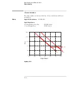
Page 168: ...t Voltage Swing 500 mV peak to peak Threshold Accuracy 2 of input signal 50 mV Minimum External Clock Period 1 ns Setup Hold Per pod 350 ps 350 ps Across pods 750 ps 750 ps 350 ps 350 ps with manual deskew Actual setup hold adjustable with sample offset in all modes For the frequency range of 62 5 MHz to 20 MHz a duty cycle of 40 to 60 is required Specifications and Characteristics Specifications ...

Page 169: ...bes Input DC Resistance 100 KΩ 2 Input Impedance DC through 400 ns rise time 100 KΩ typical 3 5 ns through 350 ps 500 Ω typical Impedance Plot 10 KHz 100 KHz 100 MHz 1 GHz 1 MHz 10 MHz 10 GHz 1000K 100K 10K 1K 100 10 500 W 0 2 pF 3 pF Ohms Edge Speed Specifications and Characteristics Characteristics 12 4 ...

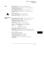
Page 170: ...es a periodic clock Minimum Detectable Pulse Width 900 ps Channel Count 16 per card up to 80 in one frame Channel to Channel Skew across up to 80 channels Per pod 250 ps typical Across pods 1 ns typical 250 ps with manual deskew Memory Depth per Channel 65536 samples State Clocks One external clock is available on the master board No clocks are available on the expander board Clock edge is selecta...

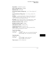
Page 171: ...riod channel to channel skew 0 005 of time interval reading Sample Period Accuracy 0 005 of sample period Channel to Channel Skew across up to 80 channels 250 ps typical Maximum Delay After Triggering 2 to the 20th sample period or 16 78 ms at or below 16 ns sample period Note When oversampling use oversampled period for sample period above Trigger Characteristics Pattern Recognizers 4 Each patter...

Page 172: ... the analyzer will branch to the specified sequence level Maximum Occurrence Count 16 777 216 Maximum Sequencer Speed 500 MHz State Sequence Levels 4 plus trace point Timing Sequence Levels 4 plus trace point Timer Counter There is one timer or counter per sequence level which is restarted upon entry into each level Timer Counter Range Timing mode 0 s to 33 ms State mode 500 MHz to 1 GHz user cloc...

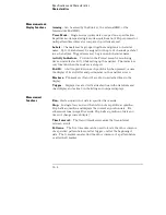
Page 173: ... the display of its slot letter and pod number on the analyzer screen Markers Two markers X and O are shown as dashed lines in the display Trigger Displayed as a red vertical dashed line in the waveform and chart display and as line 0 in the listing and compare displays Measurement Functions Run Starts acquisition of data in specified trace mode Stop In single trace mode or the first run of a repe...

Page 174: ...ference can be specified Any data bits that do not fall within the enabled channels and the specified range are not compared Stop Measurement Repetitive acquisitions may be halted when the comparison between the current acquisition and the Compare Image is equal or not equal Compare Mode Display Reference Listing display shows the Compare Reference and bit masks Difference Listing display highligh...

Page 175: ...displayed where the bit pattern occurs Range Symbols User can define a mnemonic covering a range of values When data display is SYMBOL values within the specified range are displayed as mnemonic offset from base of range Number of Symbols 1000 maximum Operating Environment Temperature Instrument 0 C to 55 C 32 F to 131 F Probe lead sets and cables 0 C to 65 C 32 F to 149 F Humidity Instrument prob...

Page 176: ...13 Installation and Service ...

Page 177: ...an cause poor operation or malfunction Provide protection against internal condensation The logic analyzer module will operate at all specifications within the temperature and humidity range given in chapter 12 However reliability is enhanced when operating the module within the following ranges Temperature 20 C to 35 C 68 F to 95 F Humidity 20 to 80 noncondensing Storage Store or ship the logic a...

Page 178: ...ement To Prepare the Mainframe C AU TI O N Turn off the mainframe power before removing replacing or installing the module C AU TI O N Electrostatic discharge can damage electronic components Use grounded wriststraps and mats when performing any service to this module 1 Turn off the mainframe power switch then unplug the power cord Disconnect any input or output connections 2 Plan your module conf...

Page 179: ...er panels Remove the cards or filler panels that are in the slots intended for the module installation Push all other cards into the card cage but not completely in This is to get them out of the way for installing the module Some modules for the Logic Analysis System require calibration if you move them to a different slot For calibration information refer to the manuals for the individual module...

Page 180: ...hen looking at back of mainframe must be used when the master card is above the expansion card the connector on the right side of the master card must be used See To Install the Module for the installation procedure To configure a three card module you can have the master card in between the expansion cards or above or below the expansion cards see illustration on page 13 4 Note the cables which a...

Page 181: ...nector on the right side of the master card must be used See To Install the Module for the installation procedure To configure a five card module the master card must go in the middle slot and two expansions cards are above it and two are below it see illustration on page 13 4 The two long cables three connectors must be used For the expansion cards above the master card use the connector on the l...

Page 182: ...e the card approximately three inches into the mainframe b Connect the appropriate interface cable long or short to the appropriate side of the card see illustration on page 13 4 Repeat steps a and b for the remaining cards 3 Slide the complete module into the mainframe but not completely in Each card in the instrument is firmly seated and tightened one at a time in step 5 4 Position all cards and...

Page 183: ... use To Test the Module If you require a test to initially accept the operation perform the self tests later in this chapter If you need to deskew the channel to channel variations go to chapter 10 Skew Adjust If you require a test to verify the specifications start at the beginning of chapter 3 Testing Performance in the optional Agilent Technologies 16517A 18A Service Guide The Service Guide is ...

Page 184: ...ations then save the configurations to disk prior to loading the PV system Refer to the Agilent Technologies 16500 16501A User s Reference for more information on saving configuration files to disk Access the Self tests 1 Disconnect all inputs then turn on the power switch if the mainframe is not turned on 2 In the System Configuration menu touch Configuration In the pop up menu touch Test If the ...

Page 185: ...dicates which module board failed Refer to chapter 8 for a description of the error messages 1 Touch Functional Tests The functional tests menu appears 2 To run all of the tests touch the All Tests field As each of the functional tests is performed and passed the status field will change from UNTESTED to PASS 3 Touch Done to exit the test menu Touch Exit to exit the Functional Tests menu Installat...

Page 186: ...s 2 Perform the skew adjust procedure Touch Adjust Clock and Data Path Skew A BNC coax cable Agilent Technologies 10503A and Calibration Pod 16517 63201 are needed Follow the instructions on the display At the end of the Skew adjust save the skew factors to NV RAM For more information refer to To Adjust the Channel to channel Skew in chapter 10 Installation and Service Perform the Skew Adjustments...

Page 187: ...s 1 Touch the 4GHz 1GHz Timing field then touch Test System 2 Touch Configuration then touch Test If the 16517A 18A module is configured in an Agilent Technologies 16500A mainframe the operating system disk must be installed in one of the flexible disk drives 3 Touch the box labeled Touch box to Exit Test System The Agilent Technologies 16500 operating system will now load and the system configura...

Page 188: ... associated with the failure symptoms 3 Package the module You can use either the original shipping containers or order materials from an Agilent Technologies sales office C AU TI O N Electrostatic discharge can damage electronic components For protection against electrostatic discharge package the module in electrostatic material 4 Seal the shipping container securely and mark it FRAGILE To Clean...

Page 189: ...13 14 ...

Page 190: ...r field 7 8 label and base fields 7 16 mask field 7 10 post processing features 7 3 reference listing field 7 4 specify stop measurement 7 11 to 7 13 configuration capabilities 1 5 configuring the analyzer 1 5 copy listing to reference field 7 7 cursor 1 4 D data roll field 5 3 7 14 delay field negative positive 6 6 description accessories supplied 1 6 difference listing field 7 5 to 7 6 display l...

Page 191: ...2 to 6 13 channel mode field 6 14 to 6 15 insert delete 6 17 module and label fields 6 16 sequential individual overlay 6 14 waveform display size 6 19 selecting waveforms delete and delete all fields 6 18 sequence levels branching 4 24 definition 4 4 editing 4 5 types 4 4 user programmable 4 17 to 4 24 4 26 set sample offset field 3 6 to 3 7 show states field 5 5 skew adjust 10 2 specifications 1...

Page 192: ...to O display field 9 7 x pattern o pattern occurrence field 9 7 waveform reconstruction 6 7 waveform size 6 19 X X to O display field 9 13 X to O field 9 7 X axis label state value field 8 9 Index Index 3 ...

Page 193: ...Index 4 ...
Page 194: ...ructions are for trained service personnel To avoid dangerous electric shock do not perform any service unless qualified to do so Do not attempt internal service or adjustment unless another person capable of rendering first aid and resuscitation is present If you energize this instrument by an auto transformer for voltage reduction make sure the common terminal is connected to the earth terminal ...

Page 195: ...ations for the product or improper site preparation or maintenance No other warranty is expressed or implied Agilent Technologies specifically disclaims the implied warranties or merchantability and fitness for a particular purpose Exclusive Remedies The remedies provided herein are the buyer s sole and exclusive remedies Agilent Technologies shall not be liable for any direct indirect special inc...

Page 196: ...C 555 3 1982 A1 1990 EN 60555 3 1987 A1 1991 IEC 801 2 1991 EN 50082 1 1992 4 kV CD 8 kV AD IEC 801 3 1984 EN 50082 1 1992 3 V m 1kHz 80 AM 27 1000 MHz IEC 801 4 1988 EN 50082 1 1992 0 5 kV Sig Lines 1 kV Power Lines Supplementary Information The product herewith complies with the requirements of the Low Voltage Directive 73 23 EEC and the EMC Directive 89 336 EEC and carries the CE marking accord...

Page 197: ...SPR 11 ISM Group 1 Class A equipment Immunity EN50082 1 Code1 Notes2 IEC 555 2 IEC 555 3 IEC 801 2 ESD 4kV CD 8kV AD IEC 801 3 Rad 3 V m IEC 801 4 EFT 0 5 kV 1kV 1 1 2 1 1 1 Performance Codes 1 PASS Normal operation no effect 2 PASS Temporary degradation self recoverable 3 PASS Temporary degradation operator intervention required 4 FAIL Not recoverable component damage 2 Notes none Sound Pressure ...

Page 198: ...quipment Have surplus equipment taking up shelf space We ll give it a new home Learn more Visit us at artisantg com for more info on price quotes drivers technical specifications manuals and documentation Artisan Scientific Corporation dba Artisan Technology Group is not an affiliate representative or authorized distributor for any manufacturer listed herein We re here to make your life easier How...

Reviews: