Trigger Position Field
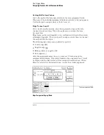
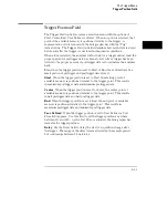
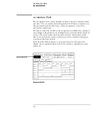
The Trigger Position field accesses a selection menu with the options of
Start, Center, End, User Defined, or Delay. When an option is selected, that
point of the available memory is positioned relative to the trigger. A
representation of this is shown by the blue graphic bar with the "Trig"
indicator line. The Trigger Position field determines how much data is stored
before and after the trigger occurs for all subsequent acquisitions.
When a Run is started, the analyzer will not look for a trigger until at least the
proper percent of pretrigger data has been stored. After a trigger has been
detected, the proper percent of posttrigger data is stored before the analyzer
halts.
Even when the trigger position is set to Start or End, there will always be a
small portion of pretrigger and posttrigger data stored.
Start
When the trigger position is set to Start, the starting point of
available memory is positioned relative to the trigger point. This results
in maximum posttrigger data and minimum pretrigger data.
Center
When the trigger position is set to Center, the center point of
available memory is positioned relative to the trigger point. This results
in half pretrigger data and half posttrigger data.
End
When the trigger position is set to End, the end point of available
memory is positioned relative to the trigger point. This results in
maximum pretrigger data and minimum posttrigger data.
User Defined
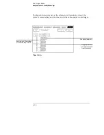
When the trigger position is set to User Defined, a Post
Store field appears. Use this field to set the trigger position any where
between 0% and 99%. As the Post Store is adjusted, the blue graphic bar
indicates the trigger position.
Delay
Use the Delay field to delay the start of acquisition storage after
the trigger. The range of the delay time is affected by the sample period
but could range between 16 ns to 8 ks.
The Trigger Menu
Trigger Position Field
4–33
Summary of Contents for 16517A
Page 3: ...The Agilent Technologies 16517A 4 GSa S Timing and 1 GSa S State Logic Analyzer ii ...
Page 5: ...iv ...
Page 11: ...Contents 6 ...
Page 12: ...1 General Information ...
Page 18: ...2 Probing ...
Page 29: ...2 12 ...
Page 30: ...3 The Format Menu ...
Page 42: ...4 The Trigger Menu ...
Page 79: ...4 38 ...
Page 80: ...5 The Listing Menu ...
Page 86: ...6 The Waveform Menu ...
Page 106: ...7 The Compare Menu ...
Page 122: ...8 The Chart Menu ...
Page 133: ...8 12 ...
Page 134: ...9 Markers and Stop Measurements ...
Page 149: ...9 16 ...
Page 150: ...10 Skew Adjust ...
Page 156: ...11 Error Messages ...
Page 165: ...11 10 ...
Page 166: ...12 Specifications and Characteristics ...
Page 176: ...13 Installation and Service ...
Page 189: ...13 14 ...
Page 193: ...Index 4 ...

