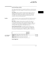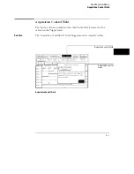
Armed By Field
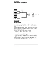
The logic analyzer can be armed by either the Run field, a Group Run through
the Intermodule Bus (IMB), or an external signal through an SMB Port
connector on the back panel.
Run/Group Run
Set the Armed By field to Run if you are using just a single analyzer to make a
measurement. When you select the Run/Stop field, you start the trigger
evaluation process immediately.
If the measurement includes other modules in the frame, and they are
configured as a Group Run in the Intermodule menu, the Run selection
becomes a Group Run selection. This type of configuration allows all
modules in the measurement to be time-correlated.
SMB Port
Set the Armed By field to the SMB Port option if you want to arm the
analyzer with an external arming signal from an outside source.
An arming signal can also come from another module within the frame, such
as an oscilloscope TRIG OUT signal. However, the only way the
measurement can be time-correlated is if both the sending and receiving
modules are configured as a Group Run in the system’s Intermodule menu.
Generally, the SMB Port is used when you want an external trigger source to
arm a module, or group of modules in the frame, or you want to take
advantage of the faster arming path.
See Also
"Intermodule Measurements" chapter in the
Agilent Technologies 16500B
User’s Reference
or "Correlating Measurements" chapter in the
Agilent
Technologies 16500C User’s Reference
for information on making a
measurement using other modules through the IMB.
4–37
Summary of Contents for 16517A
Page 3: ...The Agilent Technologies 16517A 4 GSa S Timing and 1 GSa S State Logic Analyzer ii ...
Page 5: ...iv ...
Page 11: ...Contents 6 ...
Page 12: ...1 General Information ...
Page 18: ...2 Probing ...
Page 29: ...2 12 ...
Page 30: ...3 The Format Menu ...
Page 42: ...4 The Trigger Menu ...
Page 79: ...4 38 ...
Page 80: ...5 The Listing Menu ...
Page 86: ...6 The Waveform Menu ...
Page 106: ...7 The Compare Menu ...
Page 122: ...8 The Chart Menu ...
Page 133: ...8 12 ...
Page 134: ...9 Markers and Stop Measurements ...
Page 149: ...9 16 ...
Page 150: ...10 Skew Adjust ...
Page 156: ...11 Error Messages ...
Page 165: ...11 10 ...
Page 166: ...12 Specifications and Characteristics ...
Page 176: ...13 Installation and Service ...
Page 189: ...13 14 ...
Page 193: ...Index 4 ...

