background image

LAN User’s Guide

Publication number 01660-97025
March 2000

For Safety information, Warranties and Regulatory information, see the pages
behind the index

  Copyright Agilent Technologies 1993-2000

    All Rights Reserved

Agilent Technologies
1660C/CS-Series and
1670A-Series Logic Analyzers

Summary of Contents for 1660 CS Series

Page 1: ...97025 March 2000 For Safety information Warranties and Regulatory information see the pages behind the index Copyright Agilent Technologies 1993 2000 All Rights Reserved Agilent Technologies 1660C CS...

Page 2: ...lowing equipment and software Agilent Technologies 1660C CS series logic analyzer with LAN option or Agilent Technologies 1670A series logic analyzer Ethernet local area network using TCP IP protocol...

Page 3: ...y the analyzer interface on an X Window server and describes the basics of using the interface Chapter 4 shows you how to retrieve measurement data screen images and status information from your logic...

Page 4: ...on programming the analyzer The Programmer s Guide can be ordered from your Agilent Technologies Sales Office UNIX is a registered trademark in the United States and other countries licensed exclusive...

Page 5: ...formation 3 12 4 Retrieving and Restoring Data To copy ASCII measurement data 4 3 To copy raw measurement data 4 5 To restore raw measurement data 4 6 To strip LIF structure from raw measurement data...

Page 6: ...roblems 7 21 If you cannot connect to the logic analyzer 7 21 If you cannot mount the logic analyzer file system 7 22 If you cannot access the file system via ftp 7 22 If you cannot start the X Window...

Page 7: ...1 Connecting and Configuring...

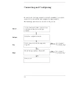
Page 8: ...wing chart shows an overview of the process No Yes No Yes Connect the RJ 45 or BNC connector from your network then turn on the logic analyzer Go to chapter 7 Troubleshooting Verify connectivity with...

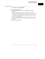
Page 9: ...r and an RJ 45 connector and resembles a standard modular phone line Thinlan uses coaxial cable If you are unsure what your network uses for its physical connection contact your local network administ...

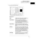
Page 10: ...nus will be stored in nonvolatile memory 1 Go to the System External I O menu and select LAN Settings a Turn on the analyzer and wait until the power up tests are complete b b Press the System key c I...

Page 11: ...omputer you wish to use it with you need to enter a gateway address File Timeout This is not the same as the network timeout which is set on the computer The logic analyzer file timeout is how long th...

Page 12: ...re requires an entry for the logic analyzer before another computer can talk to it These entries are usually kept in a file named etc hosts The etc hosts file also associates an alias with the IP addr...

Page 13: ...umentation for the exact syntax UNIX ping IP address symbolic name MS DOS ping IP address symbolic name MS Windows For a Windows environment select the ping icon in your network menu Refer to your net...

Page 14: ...the analyzer while data allows users to only read files from the file system Data users can also write files to the disk drives of the logic analyzer If you have trouble refer to chapter 7 Troublesho...

Page 15: ...er to your network documentation for more information MS DOS For a PC using MS DOS and running PC NFS use a form of the net use command For example PC NFS uses net use drive specifier IP address or a...

Page 16: ...1 10...

Page 17: ...2 Accessing the Logic Analyzer File System...

Page 18: ...trol User The control user can send programming commands The control user has read and write access to the file system There can only be one control user at any time Data User The data user cannot sen...

Page 19: ...m Computers Running the UNIX Operating System The syntax of the mount command is typically mount symbolic name IP address control data directory name The symbolic name is the host name of the logic an...

Page 20: ...puter named logic enter the following command at the UNIX command line mount 1660C_1 control logic After you have entered this command you will be able to see the logic analyzer s file system under th...

Page 21: ...ogic analyzer is set up by your system administrator Typically this name is found in the hosts file on your computer or returned by a name server It is equivalent to the logic analyzer s IP Internet P...

Page 22: ...MS Windows use the Network Connections menu in the Disk options of File Manager To connect to the logic analyzer from the File Manager in MS Windows Version 3 1 perform the following steps 1 Open File...

Page 23: ...analyzer system is mounted on followed by the analyzer s name or IP address At the end of the path specify which kind of connection you would like to establish either control or data Accessing the Lo...

Page 24: ...n is made you will be prompted for a login name Enter control or data depending on the type of access you want If you are prompted for a password just press the Return or Enter key There is no passwor...

Page 25: ...3 Using the X Window Interface...

Page 26: ...the logic analyzer s keyboard and mouse Refer to your logic analyzer s User s Guide for a complete description of keyboard and mouse operation Duplicating Front Panel Knob Control To duplicate turnin...

Page 27: ...om being displayed On computers running the UNIX operating system you can enable the analyzer to initiate windows by entering the xhost command xhost analyzer IP address On computers that aren t runni...

Page 28: ...n X Window The display number and the screen number are usually 0 The display number is not zero when you have multiple displays For some workstations screen number 1 is a black and white screen 5 Sel...

Page 29: ...screen The IP Internet Protocol address is the address of the X Windows server There are several methods for sending the XWIN ON command The easiest is using psuedo telnet but it can also be done usin...

Page 30: ...ection to the analyzer command parser which uses socket number 5025 A telnet server would normally not need to have the socket specified To start the X Window interface on the computer whose IP addres...

Page 31: ...named lp1660C in this example You will need to start the X server software on a PC and may need to enable the analyzer initiated window On a UNIX computer you will need to enable the window initiated...

Page 32: ...ramming command to the logic analyzer Note that simply closing the window that the interface is running in may leave the logic analyzer hung up Example Pseudo telnet method using a UNIX computer If yo...

Page 33: ...ive L enter the following command echo xwin off L system program Example ftp method To end the session using ftp create a second text file with the following contents xwin off cr The second text file...

Page 34: ...r documentation for instructions on loading and using custom fonts Generally the steps you will take are a Compile the BDF files into the proper format b Build the font directory FONTS DIR file c If t...

Page 35: ...es s ftp get sm165 bdf 200 PORT command ok 150 Opening data connection for lg165 bdf 15 6 253 146 1122 19595 bytes 226 Transfer complete 22311 bytes received in 0 32 seconds 68 04 Kbytes s ftp quit To...

Page 36: ...ion and restart the X Window Computers that are configured to support only 16 colors will substitute for some default colors Window Dimensions and Content The dimensions of the logic analyzer window a...

Page 37: ...4 Retrieving and Restoring Data...

Page 38: ...raw measurement data Copy screen images from system graphics Copy status information from status Copy configurations from the logic analyzer Restore configurations to the logic analyzer Measurement d...

Page 39: ...r 3 Copy the measurement data from the slot_a data asc subdirectory In the analyzer s file system ASCII data files are located in slot_a data asc analyzer name label name txt There is an ASCII data fi...

Page 40: ...r label addr_lo on your PC To copy the ASCII data to your local computer at the MS DOS prompt enter copy L slot_a data asc 68000_BUS addr_lo local path name If your computer is running the UNIX operat...

Page 41: ...to the chapter Accessing the Logic Analyzer File System 3 Copy the data raw file from the slot_a directory for analyzer data or slot_b directory for oscilloscope data Raw measurement data files are bi...

Page 42: ...scope data it would be slot_b If you copy the raw data to a different directory than you originally got it from the logic analyzer won t know how to interpret it Raw measurement data files are binary...

Page 43: ...ata raw File Format The format of the data raw file is similar to the file format described in the logic analyzer Programmer s Guide The data raw file consists of a 512 byte header followed by one or...

Page 44: ...e 1 case 2 do nothing just throw away break case 3 throw away the first two bytes record size the next four bytes file type the next 32 bytes file description if len 38 0 write 1 buffer 38 len 38 brea...

Page 45: ...te Encapsulated PostScript file in EPS version 3 0 format These graphics files contain the current display on the logic analyzer screen The contents of the files change whenever you change the display...

Page 46: ...out the Group Run and the relative trigger times of each module if applicable frame txt shows what is mapped to each slot and the operating system version mount txt lists all connections to the logic...

Page 47: ...me Code Version Card ID Code CPU System V01 00 slot_a Analyzer V01 00 032 Example An example mount txt file Analyzer name LP LAN Analyzer Hostname UID GID Directory FTP 15 6 253 137 2710 00000 00000 d...

Page 48: ...oaded into the logic analyzer later Raw configuration files are not transferrable between logic analyzer models The setup raw file is overwritten whenever you change the configuration Dynamic Configur...

Page 49: ...different directory than it came from the analyzer will not know how to interpret it Example Restoring an analyzer configuration Suppose you want to load a configuration file called 486_bus from your...

Page 50: ...4 14...

Page 51: ...5 Programming the Logic Analyzer...

Page 52: ...indeterminate amounts of time to reach their destinations There can be no guarantee that commands sent from your computer will reach the logic analyzer in a timely way For information on your logic a...

Page 53: ...t opens the socket and sends commands to it Connection to the command parser socket is by definition a control user connection Because only one control user connection is allowed you will not be able...

Page 54: ...e logic analyzer via the LAN you must set the controller to Ethernet 1 In the System External I O menu select the Connected To field in the Controller box 2 Select Ethernet from the pop up menu Select...

Page 55: ...ify the port you will get a connection refused message telnet 1660sys Trying telnet Unable to connect to remote host Connection refused To enter commands directly using telnet first open a telnet conn...

Page 56: ...1 menu MENU 1 3 system dsp Triggering on memory violation system print screen The small program above turns on the header and longform for query responses selects the analyzer checks which menu it is...

Page 57: ...the file system via ftp you can Use ftp s put command to copy a text file containing a series of commands to the system program file Example Programming the logic analyzer over an NFS mount line by l...

Page 58: ...e second command clears the format set up The third command clears the trigger set up Now copy the file to the logic analyzer At the MS DOS prompt enter copy clear txt L system program If your compute...

Page 59: ...n the system program file To retrieve information from queries create a text buffer open the system program file and read the contents of the file into the buffer In C you can use read or getstr to re...

Page 60: ...FILE file int num char receive_str STR_LEN Send a query and retrieve and print the response file fopen logic system program r while getstr file receive_str 0 fclose file file fopen logic system progra...

Page 61: ...start n putstr file mach1 twav range 100 ns n fclose file sleep 2 file fopen logic system program r while getstr file receive_str 0 fclose file printf s n receive_str Programming the Logic Analyzer T...

Page 62: ...nds the IDN query command to request the instrument s identity include stdio h include sys types h include sys socket h include netinet in h typedef struct sockaddr_in tdSOCKET_ADDR define PARSER_PORT...

Page 63: ...OCKET_ADDR serv_addr sizeof serv_addr Send a message from the created socket send sockfd cmdString strlen cmdString 0 Receive a message from the 16500B socket recv sockfd receiveBuffer sizeof receiveB...

Page 64: ...5 14...

Page 65: ...6 Concepts...

Page 66: ...Concepts This chapter describes Directory structure of the logic analyzer s file system Dynamic files New fields in the logic analyzer s system menus 6 2...

Page 67: ...t_a directory for the state timing analyzer The Agilent Technologies 1660CS series also have a slot_b directory for the oscilloscope slot_x data raw Binary measurement data files You can save and rest...

Page 68: ...machine1 and machine2 but they will change whenever the analyzer names are changed in the Configuration Menu Analyzer Directory Structure Label Data Files slot_a data asc analyzer name label txt Both...

Page 69: ...zero at line number 0 You can use this information to align data from different measurements Time Tag and State Tag Data If time tags have been turned on the time_abs txt file contains a column of ti...

Page 70: ...when working with the dynamic files from the logic analyzer The complete display may appear incorrect during file transfers This does not affect the transfer or the contents of the file Once you have...

Page 71: ...at you can configure the logic analyzer to work with your network The LAN Settings menu is explained in Chapter 1 Connecting and Configuring Time Zone Field With LAN a field labeled Time Zone appears...

Page 72: ...6 8...

Page 73: ...7 Troubleshooting...

Page 74: ...hooting This chapter provides troubleshooting information for the LAN interface It is arranged in three sections Troubleshooting the initial connection Solutions to common problems Getting service sup...

Page 75: ...er single client network point to point You can connect the logic analyzer to a single server single client network In this configuration the client is running an NFS application program If you have d...

Page 76: ...ble to read the logic analyzer remote file server directory go directly to the troubleshooting section relating to your network in this chapter If you have been able to read the logic analyzer remote...

Page 77: ...will be a total of 9 10 or possibly 11 packets received with a minimal average of round trip time The minimal average will be different from network to network LAN traffic will cause the round trip t...

Page 78: ...te file server If the logic analyzer still does not respond to ping then you should suspect a hardware problem with the logic analyzer To check the logic analyzer performance refer to Verify the logic...

Page 79: ...the command syntax before continuing with the troubleshooting If the syntax is correct then resolve the error messages using your network documentation Verify that all of the mounting rules are being...

Page 80: ...ware documentation for more information ping IP address 10 Normal Response A normal response to the ping will be a total of 9 10 or possibly 11 packets received if 10 echo requests were specified Beca...

Page 81: ...in this chapter Intermittent Response On a multiclient network receiving 1 to 8 packets indicates a problem with the network Because the number of packets received depends on your network traffic and...

Page 82: ...that all of the mounting rules are being followed Refer to the documentation of your network platform for the mounting rules A Device Busy error message appears when you try to mount as control if som...

Page 83: ...Refer to your NFS software documentation for more information Normal Response A normal response to the ping will be a total of 9 10 or possibly 11 packets received if 10 echo requests were specified B...

Page 84: ...this chapter Intermittent Response On a multiclient network receiving 1 to 8 packets indicates a problem with the network Because the number of packets received depends on your network traffic and in...

Page 85: ...refer to the documentation for MS DOS Normal Response When Connect is selected the drive letter and the mounted remote file server should appear under the Network Drive Connections window Error Messa...

Page 86: ...eceived then the physical connection is considered good If EtherTwist 10Base T is used then the logic analyzer will listen for the heartbeat signal from the LAN If a heartbeat is received then the phy...

Page 87: ...ct Sys PV from the pop up 6 Select External I O and then select System Test from the pop up 7 Select LAN Test then select Run 8 Verify that the tests pass If all of the tests pass then go to the next...

Page 88: ...ber The following figure shows the bit positions of the hexidecimal status word A 1 in a bit position signifies that the bit is set and the test failed A 0 in a bit position signifies that the bit is...

Page 89: ...cted that the LAN cable is properly connected to the LAN board If this bit is set then the physical connection of the LAN cable must be checked Bit 3 If the Termination bit is set then the self test h...

Page 90: ...it is used in conjunction with bits 4 5 and 6 Refer to the appropriate bit for the suggested course of action Bit 9 The Rx bit indicates whether the receive portion of the MAC ENDEC or TRANS test fail...

Page 91: ...Statistics menu 1 Go to the System External I O menu 2 Select LAN Settings 3 Select Ethernet Statistics from the bottom of the pop up menu See the Ethernet Statistics information on the next page for...

Page 92: ...and retransmission is attempted After 15 deferrals the not successful field is incremented Deferred Number of packets deferred due to network traffic After 15 deferrals the not successful field is in...

Page 93: ...n verify the network connection by using the ping command or another similar echo request utility If a bad connection is revealed Make sure the logic analyzer is on Check the physical connection to th...

Page 94: ...Analyzer Configuration menu is displayed before attempting the mount Verify the LAN connection between your computer and the logic analyzer Refer to If you cannot connect to the logic analyzer earlie...

Page 95: ...have to enter an xhost IP address command on your X server machine If your X Window looks odd If certain of the symbols such as the activity indicators look odd Load the X Window fonts See To load cu...

Page 96: ...u cannot telnet to the command parser socket If you get a connection refused message Verify that you included the telnet port number 5025 in the command If you get a connection timed out or no respons...

Page 97: ...ections Check to see if many other users are currently connected to the system If the logic analyzer does not respond When the logic analyzer is transmitting a large file such as a deep memory acquisi...

Page 98: ...se or next day response The support contracts are available for economical support beyond the 90 day warranty period Contact your nearest Agilent Technologies Sales Office for information regarding su...

Page 99: ...he user or system administrator IP Address Internet Protocol Ad dress A unique number that is assigned to a each device which is to be connected to a TCP IP network Before using your logic analyzer on...

Page 100: ...networks telnet A protocol that allows users to create a session to run programs on or transfer information to and from a remote computer time out A period of system inac tivity during which the syst...

Page 101: ...ta raw 7 24 Device Busy 7 22 in MS Windows 7 13 in MS DOS 7 10 Device Busy message in workstations 7 7 Device Timeout 7 3 directory structure logic analyzer 6 3 to 6 5 display copying 4 9 drive name 2...

Page 102: ...13 error messages from mount 7 13 error messages from ping 7 11 File Manager 2 6 hostname 7 11 intermittent response from ping 7 12 mount 1 9 2 6 7 13 no response from ping 7 12 normal response from...

Page 103: ...e 2 3 to 2 7 7 22 state tags 6 5 status bits 7 17 status information 4 10 to 4 11 status number description 7 16 status reporting message See status number SUN workstations 6 6 support services 7 26 s...

Page 104: ...Index Index 4...
Page 105: ...gerous electric shock do not perform any service unless qualified to do so Do not attempt internal service or adjustment unless another person capable of rendering first aid and resuscitation is prese...

Page 106: ...implied Agilent Technologies specifically disclaims the implied warranties of merchantability or fitness for a particular purpose Exclusive Remedies The remedies provided herein are the buyer s sole a...

Reviews: