To remove and replace the optional GPIB and RS-232C cables
1
Using previous procedures, remove the following assemblies:
•
Handle
•
Rear Feet
•
Cover
•
Disk Drive
•
Power Supply
•
Rear Panel
2
Disconnect interface cables from the main circuit board.
3
Remove the two hex standoffs connecting the GPIB cable, then slide the GPIB cable
forward and out of the rear panel.
4
Remove the two hex standoffs connecting the RS-232C cable, then slide the RS-232C
cable forward and out of the rear panel.
5
Reverse this procedure to install the GPIB and RS-232C cables.
Replacing Assemblies
To remove and replace the optional GPIB and RS-232C cables
6–13
Summary of Contents for 1664A
Page 3: ...The Agilent Technologies 1664A Logic Analyzer iii...
Page 8: ...Contents viii...
Page 22: ...2 6...
Page 91: ...Troubleshooting Flowchart 1 Troubleshooting To use the flowcharts 5 3...
Page 92: ...Troubleshooting Flowchart 2 Troubleshooting To use the flowcharts 5 4...
Page 93: ...Troubleshooting Flowchart 3 Troubleshooting To use the flowcharts 5 5...
Page 94: ...Troubleshooting Flowchart 4 Troubleshooting To use the flowcharts 5 6...
Page 95: ...Troubleshooting Flowchart 5 Troubleshooting To use the flowcharts 5 7...
Page 96: ...Troubleshooting Flowchart 6 Troubleshooting To use the flowcharts 5 8...
Page 97: ...Troubleshooting Flowchart 7 Troubleshooting To use the flowcharts 5 9...
Page 98: ...Troubleshooting Flowchart 8 Troubleshooting To use the flowcharts 5 10...
Page 99: ...Troubleshooting Flowchart 9 Troubleshooting To use the flowcharts 5 11...
Page 100: ...Troubleshooting Flowchart 10 Troubleshooting To use the flowcharts 5 12...
Page 101: ...Troubleshooting Flowchart 11 Troubleshooting To use the flowcharts 5 13...
Page 102: ...Troubleshooting Flowchart 12 Troubleshooting To use the flowcharts 5 14...
Page 124: ...Exploded View of the 1664A Replacing Assemblies 6 4...
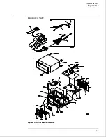
Page 137: ...Exploded View Exploded view of the 1664A logic analyzer Replaceable Parts Exploded View 7 3...
Page 160: ...8 18...
Page 162: ......

