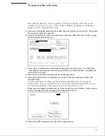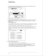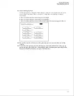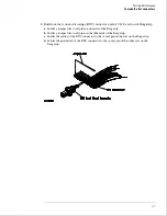
Test the 0 V User threshold
1
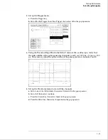
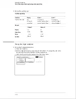
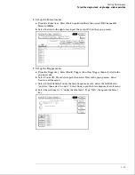
Move the cursor to the field to the right of Pod 1. Type 0, then press the Select key.
2
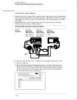
On the function generator front panel, enter +0.102 V
±
1 mV DC offset. Use the
multimeter to verify the voltage.
The activity indicators for pod 1 should show all data channels and the J-clock channel at a
logic high.
3
Using the Modify down arrow on the function generator, decrease offset voltage in
1-mV increments until all activity indicators for pod 1 show the channels at a logic
low. Record the function generator voltage in the performance test record.
4
Using the Modify up arrow on the function generator, increase offset voltage in
1-mV increments until all activity indicators for pod 1 show the channels at a logic
high. Record the function generator voltage in the performance test record.
Testing Performance
To test the threshold accuracy
3–15
Summary of Contents for 1664A
Page 3: ...The Agilent Technologies 1664A Logic Analyzer iii...
Page 8: ...Contents viii...
Page 22: ...2 6...
Page 91: ...Troubleshooting Flowchart 1 Troubleshooting To use the flowcharts 5 3...
Page 92: ...Troubleshooting Flowchart 2 Troubleshooting To use the flowcharts 5 4...
Page 93: ...Troubleshooting Flowchart 3 Troubleshooting To use the flowcharts 5 5...
Page 94: ...Troubleshooting Flowchart 4 Troubleshooting To use the flowcharts 5 6...
Page 95: ...Troubleshooting Flowchart 5 Troubleshooting To use the flowcharts 5 7...
Page 96: ...Troubleshooting Flowchart 6 Troubleshooting To use the flowcharts 5 8...
Page 97: ...Troubleshooting Flowchart 7 Troubleshooting To use the flowcharts 5 9...
Page 98: ...Troubleshooting Flowchart 8 Troubleshooting To use the flowcharts 5 10...
Page 99: ...Troubleshooting Flowchart 9 Troubleshooting To use the flowcharts 5 11...
Page 100: ...Troubleshooting Flowchart 10 Troubleshooting To use the flowcharts 5 12...
Page 101: ...Troubleshooting Flowchart 11 Troubleshooting To use the flowcharts 5 13...
Page 102: ...Troubleshooting Flowchart 12 Troubleshooting To use the flowcharts 5 14...
Page 124: ...Exploded View of the 1664A Replacing Assemblies 6 4...
Page 137: ...Exploded View Exploded view of the 1664A logic analyzer Replaceable Parts Exploded View 7 3...
Page 160: ...8 18...
Page 162: ......


