background image


161

Using the Pattern Generator

Building Test Vectors and Macros

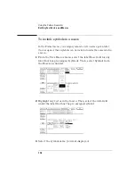
To include software instructions in a sequence

The following software instructions are available:

User Macro

Repeat Loop

If you are inserting a User Macro and have not yet built the macro, go 
to "To build a user macro" later in this chapter. Macros must be built 
before they can be inserted. To include these instructions in a 
sequence, use the following procedure.

1

Highlight the vector that will be output at the time of the 
instruction.

2

Select the INST field.

3

Select the desired software instruction to insert.

4

If required, select any qualifying actions for the instruction.

Summary of Contents for 1670E Series

Page 1: ...d 1670E Series Logic Analyzers Publication Number 01660 97028 August 1998 For Safety information Warranties and Regulatory information see the pages behind the index Copyright Hewlett Packard Company...

Page 2: ...ls and 6 clock data channels in the HP 1661E 64 data channels and 4 clock data channels in the HP 1662E 32 data channels and 2 clock data channels in the HP 1663E 3 5 inch flexible disk drive and 2 GB...

Page 3: ...asurements displays time between markers acquires until specified time between markers in captured performs statistical analysis on time between markers Lightweight miniprobes Pattern Generator Featur...

Page 4: ...channels and 4 clock data channels in the HP 1672E 3 5 inch flexible disk drive 2 GB hard disk drive HP IB RS 232 C parallel printer and LAN interfaces BNC and TP LAN ports Variable setup hold time 1...

Page 5: ...rs 12 through 14 provides a basic service guide Section 2 Chapters 15 through 16 provides information about connecting the logic analyzer to the network Chapter 17 shows you how to access the logic an...

Page 6: ...6 In This Book...

Page 7: ...onnecting Peripherals 38 To connect a mouse 39 To connect a keyboard 40 To connect to an HP IB printer 41 To connect to an RS 232 C printer 43 To connect to a parallel printer 45 To connect to a contr...

Page 8: ...sign terms to an analyzer 74 To define a term 76 To change the trigger specification 77 Changing the Trigger Sequence 79 To add sequence levels 80 To change macros 82 Setting Up Time Correlation betwe...

Page 9: ...Oscilloscope 100 Calibrating the oscilloscope 101 Calibration PROTECT UNPROTECT switch 101 Set up the equipment 101 Load the default calibration factors 102 Self Cal menu calibrations 103 Protect the...

Page 10: ...unt field 124 Auto Trig field 125 When field 126 Count field 129 The Scope Marker Menu 130 Manual time markers options 130 Automatic time markers options 133 Manual Automatic Time Markers option 138 V...

Page 11: ...include software instructions in a sequence 159 To include a user macro in a sequence 160 To build a user macro 161 To modify a macro name 162 To edit a macro 162 To add delete or rename parameters 16...

Page 12: ...all of a recursive function 204 To trigger on entry to a function 206 To capture a write of known bad data to a particular variable 208 To trigger on a loop that occasionally runs too long 209 To veri...

Page 13: ...ly 226 To trigger timing analysis of a count down on a set of data lines 227 To monitor two coprocessors in a target system 228 Special Displays 230 To interleave trace lists 231 To view trace lists a...

Page 14: ...system description 259 Assembling the probing system 263 Oscilloscope probes 267 Connecting the pattern generator pods directly to a PC board 268 Pattern generator output pod characteristics 269 Keyb...

Page 15: ...n and Luminosity Fields 302 Returning to the Default Colors 302 The Analyzer Configuration Menu 303 Type field 303 Illegal configuration 304 The Analyzer Format Menu 305 Pod threshold field 305 State...

Page 16: ...l field 338 Count field State only 340 The Listing Menu 341 Markers 341 The Waveform Menu 343 sec Div field 343 Accumulate field 343 Delay field 344 Waveform label field 344 Waveform display 346 The M...

Page 17: ...oftware 360 What is System Performance Analysis 362 Getting started 365 SPA measurement processes 367 Using State Overview State Histogram and Time Interval 383 Using SPA with other features 393 11 Lo...

Page 18: ...cquisition board theory 424 Oscilloscope board theory 428 Pattern Generator board theory 433 Self tests description 436 12 Troubleshooting the Logic Analyzer Troubleshooting the Logic Analyzer 438 Ana...

Page 19: ...annels per label 450 Timer is off in sequence level n where it is used 451 Timer is specified in sequence but never started 451 Inverse assembler not loaded bad object code 451 Measurement Initializat...

Page 20: ...hooting 475 To use the flowcharts 476 To check the power up tests 478 To run the self tests 479 To test the auxiliary power 488 SECTION 2 15 Introducing the LAN Interface Introducing the LAN Interface...

Page 21: ...rt the interface from the computer 517 To close the interface 520 To load the custom fonts 521 Additional Information 524 19 Retrieving and Restoring Data Using the LAN Retrieving and Restoring Data U...

Page 22: ...structure of the logic analyzer s file system 547 Dynamic files 550 LAN related fields in the logic analyzer s menus 551 22 Troubleshooting the LAN Connection Troubleshooting the LAN Connection 554 Tr...

Page 23: ...If the logic analyzer begins to operate slowly 575 If the logic analyzer does not respond 575 If all else fails 576 Getting Service Support 577 HP on site service 577 Return to HP service 577 SECTION...

Page 24: ...mbol Utility Features and Functions Symbol Utility Features and Functions 608 The OMF Symbol File Load Menu 609 OMF File Field 610 Drive Field 610 Label Field 611 Module Field 611 Load Field 612 Curre...

Page 25: ...Contents 25 The General Purpose ASCII File Format 625 Creating a GPA Symbol File 626 GPA File Format 627 Sections 629 Functions 631 Variables 632 Source Line Numbers 633 Start Address 634 Comments 634...

Page 26: ...26 Contents...

Page 27: ...27 Section 1 Logic Analyzer...

Page 28: ...28...

Page 29: ...29 1 Logic Analyzer Overview...

Page 30: ...he type of field currently highlighted If the field is an option field the Select key brings up an option menu or if there are only two possible values toggles the value in the field If the highlighte...

Page 31: ...y Knob The knob can be used in some fields to change values These fields are indicated by a side view of the knob placed on top of the field when it is selected The knob also scrolls the display and m...

Page 32: ...r Connector Standard Centronics connector for connecting a parallel printer Oscilloscope Calibration Port Provides signals for operational accuracy calibration for the oscilloscope and the oscilloscop...

Page 33: ...gic analyzer to physically map the target system to the channels in the logic analyzer Attach probes to a pod in a way that keeps logically related channels together Remember to ground the pod See Als...

Page 34: ...clocks Set the state and timing analyzers using the Analyzer Format menu In general these modes trade channel count for speed or storage The state analyzer also provides for complicated clocking If yo...

Page 35: ...logic analyzer Set up trigger sequence Create a sequence of steps that control when the logic analyzer starts and stops storing data and filters which data it will store For common tasks you can use...

Page 36: ...led If nothing happens see Troubleshooting the Logic Analyzer When you start a run your analyzer menu changes to one of the display menus or a status message pops up If nothing happens press the Stop...

Page 37: ...en specify the pattern When you switch views the markers keep their settings Correlate data You can correlate data by setting Count Time in your state analyzer s Trigger menu and then using interleavi...

Page 38: ...cks To use the markers select the appropriate marker type in the display menu and specify the data patterns for the marker To use SPA go to the SPA menu select the most appropriate mode fill in the pa...

Page 39: ...39 2 Connecting Peripherals...

Page 40: ...ouse and keyboard with standard DIN connector The DIN connector is the type commonly used by personal computer accessories Printers The logic analyzer communicates directly with HP PCL printers suppor...

Page 41: ...use box is on the right side above the Settings fields If the logic analyzer was displaying the System External I O menu when you plugged in the mouse the menu won t update until you exit and then ret...

Page 42: ...de above the Settings fields If the logic analyzer was displaying the System External I O menu while you plugged the keyboard in the menu won t update until you exit and then return to it The keyboard...

Page 43: ...he analyzer and the printer and connect an HP IB cable from the printer to the HP IB connector on the analyzer rear panel 2 Turn on the analyzer and printer 3 Make sure the printer is set to Listen Al...

Page 44: ...he top field of the pop up select the type of printer you are using If you are using an Epson graphics printer or an Epson compatible printer select Alternate d If the default print width and page len...

Page 45: ...wn to the 0 position For the HP ThinkJet printer the mode switches are on the rear panel of the printer Push all the switches down to the 0 position For the HP LaserJet printer the factory default swi...

Page 46: ...nter other than QuietJet the listings are printed in a compressed mode QuietJet printers can print 132 characters per line without going to compressed mode but require wider paper e Press Done 5 Selec...

Page 47: ...r is not already set to Parallel select the field under Connected To in the Printer box and choose Parallel from the menu b Select the Printer Settings field c In the top field of the pop up select th...

Page 48: ...he cable must be a null modem cable If you do not have a null modem cable you can purchase an adapter at any electronics supply store 2 Turn on the logic analyzer and then the controller 3 In the Syst...

Page 49: ...49 3 Using the Logic Analyzer...

Page 50: ...g the Logic Analyzer Using the Logic Analyzer This chapter shows you how to perform the basic tasks necessary to make a measurement Each section uses an example to show how the task fits into the over...

Page 51: ...mode and so is called the menu field For example if you are in Analyzer mode the menus for the analyzer are accessed from the menu field Menus are referred to by the titles that appear in the mode an...

Page 52: ...ct the mode field Use the arrow keys to highlight the mode field then press the Select key Or if you are using the mouse click on the field This operation is referred to as select A pop up menu appear...

Page 53: ...connect to a printer and controller Utilities allows you to set the clock update the operating system software and adjust the display Test displays the installed software version number and loads the...

Page 54: ...e and the SPA menu requires an analyzer set to SPA Configuration is always available in Analyzer mode Use Configuration to assign pods and set the analyzer type Format is available whenever an analyze...

Page 55: ...screte lines Chart is available only when an analyzer is set to State Use Chart to view your measurement as a graph of states versus time SPA is available only when an analyzer is set to SPA Use SPA t...

Page 56: ...alyzers give you the ability to separate or group data channels and label the groups with a name that is meaningful to your measurement Labels also assist you in triggering only on states of interest...

Page 57: ...bels heading In the pop up menu select Modify Label 3 Use the front panel to enter a name for the label and press Done In this example the label is called CYCLE 4 Select the pod containing the channel...

Page 58: ...r Menus 5 Toggle the channel s group status by pressing Select The indicator changes and the selector moves to the next channel In this example the channels 3 1 and 0 Pod A1 are assigned to label CYCL...

Page 59: ...ed If you get a message No labels specified check that you have at least one label turned on with channels assigned to it 2 In the Symbol menu select the Label field In the pop up menu select the labe...

Page 60: ...field and use the keypad to enter an appropriate value in the selected base Use X for don t care 8 When the pattern is specified press Done If you created additional Symbols repeat steps 6 and 7 unti...

Page 61: ...he Analyzer Waveform menu 3 To adjust the horizontal axis sec Div or states Div use the knob If nothing happens when you turn the knob make sure the Div field has a roll indicator above it as in the f...

Page 62: ...rectangle under the Div field In the pop up select Insert and then select the labels and channels The Sequential field inserts all the channels of the label as individual waveforms the Bus field group...

Page 63: ...Logic Analyzer Using the Analyzer Menus Example The following example shows a state waveform from the Hewlett Packard analysis probe for the Motorola 68360 Notice how the bus waveforms insert symbols...

Page 64: ...press the Run key to acquire data In any mode other than Analyzer Scope or Patt Gen pressing the Run key has no effect The menus which ignore Run lack the Run field onscreen In Analyzer mode with Run...

Page 65: ...er and positive numbers occurred after 5 If the labels have symbols associated with them set the base to Symbol The symbols you defined appear in the listing 6 To insert a label select one of the labe...

Page 66: ...e Motorola 68360 The ADDR label has the base set to Hex to conserve space on the display The DATA label has the base set to Invasm for inverse assembly The FC label has the base set to Symbol Addition...

Page 67: ...essing the Run key has no effect The menus which ignore Run lack the Run field onscreen In Analyzer mode with Run available the menu changes to a display menu 2 Go to the Analyzer Compare menu select...

Page 68: ...e illustration The light typeface shows the data from the compare file that is different from the data in the reference file 5 Select the Find Error field and use the knob to scroll through the errors...

Page 69: ...or the analysis probe sets up the logic analyzer to provide certain types of information for the inverse assembler This section is provided in case you ever have to set up an analyzer for inverse asse...

Page 70: ...to not work Inverse Assembly Synchronization When you press the Invasm key to begin inverse assembly of a trace the inverse assembler begins with the first displayed state in the trace list This is ca...

Page 71: ...n This may cause differences in the trace list above and below the point where you synchronized inverse assembly The best way to ensure correct inverse assembly is to synchronize using the first state...

Page 72: ...72 Using the Logic Analyzer The Inverse Assembler...

Page 73: ...73 4 Using the Trigger Menu...

Page 74: ...up your own triggers This chapter provides examples of triggering Those examples assume you already know where to find fields in the trigger menu This chapter shows you how to Specify a basic trigger...

Page 75: ...kly be tailored by specifying a particular pattern to look for instead of the general case Customizing a trigger generally requires these steps Assign terms Define the terms Change the trigger to use...

Page 76: ...analyzers in your measurement you need to assign some of the terms to Analyzer 2 1 Go to the Trigger Machine 1 menu If you have renamed Machine 1 in the Analyzer Configuration menu the name you change...

Page 77: ...igger 4 To change a term assignment select the term field The term fields toggle from one section to the other You can get all your terms assigned at once or just change a few to meet immediate needs...

Page 78: ...labels in the Analyzer Format menu If the channels you want to monitor are not attached to a label they will not appear in the trigger menu 2 Enter the value or pattern you want to trigger on If the l...

Page 79: ...nce Level menu pops up It shows the current specification for that trigger level 2 Select the field you want to change In the top row of the pop up are three action fields Insert Level Select New Macr...

Page 80: ...80 Using the Trigger Menu Specifying a Basic Trigger 4 Select Done until you are back at the Trigger menu Term Selection Pop up Menu...

Page 81: ...basic trigger you can Add sequence levels Change macros Your logic analyzer provides a macro library to make setting up the trigger easier There are 12 state macros and 13 timing macros Most macros t...

Page 82: ...n the analyzer configuration and the level specification However all Sequence Level pop ups have an Insert Level field in the upper left corner 2 Select Insert Level Another pop up offers the choices...

Page 83: ...83 Using the Trigger Menu Changing the Trigger Sequence 5 Fill in the fields and select Done Sequence Level Pop up Menu...

Page 84: ...ct Done A new Sequence Level pop up appears Its contents reflect the macro you just selected The wording of this screen is very similar to the macro description and the line drawing demonstrates what...

Page 85: ...l when you want to store different sorts of data for each trace but see how they are related For instance you could set up a timing and a correlated state analyzer and see if setup and hold times are...

Page 86: ...correlate data based on states even when they are identically defined 1 In the Analyzer Trigger menu select Count Count may be Count Off Count Time or Count States Selecting the field causes a pop up...

Page 87: ...Time turned on The timing analyzer automatically keeps track of time 1 In the state Analyzer Trigger menu select Count Count may be Count Off Count Time or Count States Selecting the field causes a p...

Page 88: ...trigger The External Trigger Output port is also referred to as Port Out It uses standard TTL logic signal levels and will generate a rising edge when trigger conditions are met 2 In the Analyzer Trig...

Page 89: ...ose Group Run This allows you to time correlate the data from the analyzers and the scope The Scope Trigger Mode must be Immediate for correlation 4 Select the field of the instrument which will arm t...

Page 90: ...CH to run from Group Run TIME MACH to run from STATE MACH and Scope Arm In to Analyzer Arming with two analyzers and an oscilloscope When the run starts the state analyzer automatically begins evaluat...

Page 91: ...nt when the sequence levels are already in place 1 Connect a BNC cable from the instrument which will be sending the signal to the External Trigger Input port on the back of the logic analyzer CAUTION...

Page 92: ...5 Select Done until you are back at the Trigger menu Arming a logic analyzer versus OR d trigger If one analyzer is set to send the PORT OUT arm and that analyzer is also set to wait for an arm from...

Page 93: ...d every last bit of memory you can get on the logic analyzer There are three simple ways to maximize memory when specifying your trigger Selectively store branch conditions State only To set the memor...

Page 94: ...not store the branch conditions You cannot set the analyzer to store only some branches in a trigger sequence specification 1 In the Analyzer Trigger menu select Acquisition Control The Acquisition C...

Page 95: ...95 Using the Trigger Menu Managing Memory 4 Select Done Acquisition Control Menu with Branches Field Highlighted...

Page 96: ...ore context but takes longer to fill more time to display and more time for you to analyze The Memory Length field allows you to configure the acquisition memory to suit your needs 1 In the Analyzer T...

Page 97: ...ved tags Tags are non interleaved if there is an unassigned pod pair or a pod pair assigned to an analyzer that is turned off 2 With interleaved tags Mode Memory Full channel timing 1 040 384 1 M Half...

Page 98: ...and an explanation If Acquisition has been customized it has 3 or 4 fields and a picture showing where the trigger is currently placed in memory 2 If the mode is Automatic select the field to toggle...

Page 99: ...99 Using the Trigger Menu Managing Memory 5 Select Done Acquisition Control Menu with Trigger Position Pop up for a Timing Analyzer...

Page 100: ...Acquisition Control menu pops up If the acquisition mode is set to Automatic the menu contains a single field and an explanation If Acquisition has been customized it has 3 or 4 fields and a picture s...

Page 101: ...101 5 Using the Oscilloscope...

Page 102: ...ng the Oscilloscope Using the Oscilloscope Using the Oscilloscope This chapter covers the oscilloscope common menus and calibration This chapter covers Calibrating the oscilloscope Oscilloscope common...

Page 103: ...ibration can be stored to nonvolatile RAM Set up the equipment 1 Turn on the logic analyzer Let it warm up for 30 minutes if you have not already done so 2 Facing the front panel reach around to the l...

Page 104: ...UNPROTECT switch on the back of logic analyzer must be set to UNPROTECT 1 Go to the Scope Calibration menu 2 Select the Mode field then select Service Cal from the pop up menu 3 Select the Procedure f...

Page 105: ...Null for channel 2 and the Logic Trigger 1 Optimize Vert Cal of the Self Cal a Connect two BNC 50 W 9 inch cables to the BNC tee adapter Connect the BNC 50W f f adapter to the BNC tee adapter and con...

Page 106: ...After completing all of the channel delay calibrations remove the cable from the oscilloscope 3 Optimize the Time Null of the Self Cal a Connect two BNC 50 W 9 inch cables to the BNC tee adapter Conn...

Page 107: ...nstrument c Select the Procedure field then select Logic Trigger from the pop up menu d Select the Start field and follow the instructions on the display e After completion of the Logic Trigger calibr...

Page 108: ...8000 sample waveform record is acquired in a single acquisition Each channel has a memory capacity of 8000 samples Repetitive mode acquisition fills acquisition memory with 8000 samples of the input...

Page 109: ...ingle or repetitive that was last chosen using the Run options If no run mode has been chosen prior to choosing autoscale the run mode defaults to single mode If you have been using the Run key to ini...

Page 110: ...channel is selected the data is acquired and the waveforms are displayed Finding the vertical settings The autoscale algorithm sets the vertical scaling V Div and offset appropriate to the input signa...

Page 111: ...uto triggered The automatic trigger mode allows the oscilloscope to sweep automatically and to display a baseline anytime a trigger signal is not present All other settings are restored to their origi...

Page 112: ...the display from 500 ps div to 5 sec div Sweep speed is measured in seconds per division Delay field The Delay field allows you to set the horizontal position of the displayed waveform in relation to...

Page 113: ...is the dc voltage that is added to or subtracted from the input signal so that the waveform can be centered on the waveform display Offset range and resolution are dependent on vertical sensitivity V...

Page 114: ...on the display V div offset trigger level are automatically adjusted to reflect the attenuation factor The marker and automatic measurement voltage values change when a Run is initiated and the next a...

Page 115: ...t field a pop up appears offering choices of TTL ECL and User The Preset field automatically sets offset V div and trigger level values to properly display TTL and ECL logic levels Trigger level is in...

Page 116: ...acquires waveform data and displays the waveform acquired from that data New acquisitions overwrite old data Average mode In Average mode the oscilloscope averages new data with previously acquired d...

Page 117: ...veform display of another time correlated module such as the timing analyzer the waveform will not continue to average Only the most recent acquisition not the average trace data will appear on the sc...

Page 118: ...ecting the Connect Dots field toggles the field between On and Off Grid field The oscilloscope display can be set to Grid On or Grid Off Selecting the Grid field toggles the field between On and Off I...

Page 119: ...ns Set Channel Labels Selecting Set Channel Labels from the Display Options pop up will take you to the Scope Channel Labels menu This menu allows you to assign labels to each of the oscilloscope chan...

Page 120: ...represents a delay time of zero seconds If you set Delay time to greater than 5 times the setting for s Div the trigger marker will move off the screen Mode Arm menu The Mode Arm field provides a pop...

Page 121: ...tern shown in the Pattern row shows the trigger condition of the input above it in the Channel row You must set the trigger voltage level for each input you want to use in the pattern To set the volta...

Page 122: ...set to Off This event will never occur in the hardware Do not confuse XX with don t care trigger on anything Immediate trigger mode Immediate trigger mode causes the oscilloscope to trigger by itself...

Page 123: ...amplitude the trigger point cannot be found If Auto Trig is set to On this causes the waveform display to become unsynchronized and to float on the display If Auto Trig is set to Off the message Waiti...

Page 124: ...s If the trigger source channel is displayed in the waveform area of the screen the trigger level marker will appear on the screen as a horizontal dashed line The trigger level marker will move up and...

Page 125: ...ple if inputs are connected to both channels 1 and 2 the Source field defaults to 1 However if an input signal is only connected to channel 2 the Source field defaults to 2 when you automatically scal...

Page 126: ...e trigger level as a trigger qualifier When the oscilloscope detects the trigger qualifier it will trigger at a user specified number of edges Count field on the waveform Count can be set to any integ...

Page 127: ...ered is displayed if one of the following conditions occurs No signal is on the input In this case the oscilloscope will display a baseline There is a signal but the specified trigger condition has no...

Page 128: ...unt field When Exited When this field is active the oscilloscope triggers on the first transition that causes the pattern specification to be false for every input used in the pattern trigger specific...

Page 129: ...e widths 80 ns 150 ns 50 ns 75 ns 20 ns 200 ns would trigger on the trailing edge of the 75 ns pulse In this example the 150 ns pulse meets the duration specification and is count 1 the 50 ns pulse is...

Page 130: ...ation and is count 1 the 150 ns pulse is count 2 and the 50 ns pulse is count 3 Range When this field is active the scope triggers on the first transition that causes the pattern specification to be f...

Page 131: ...pecification of 60 ns 100 ns and a count of 3 a pulse string with pulse widths 200 ns 80 ns 150 ns 50 ns 75 ns 20 ns would trigger on the trailing edge of the 50ns pulse In this example the 80 ns puls...

Page 132: ...x to To Trig to X and Trig to O These fields allow you to position the Tx Time X marker and the To Time O marker by entering time values for these markers Tx to To field The Tx to To field displays th...

Page 133: ...ges showing the time difference between the Tx and To markers If the time displayed in the Tx to To field is negative the To marker is to the left of the Tx marker When you select the Tx to To field a...

Page 134: ...ime markers If only one set of markers is turned on only one of the two blocks will appear on the screen On the marker menu if time markers are turned off the Sample Period display will appear on the...

Page 135: ...typically not the same as the peak to peak voltage value The oscilloscope determines the top and base voltages by finding the flattest portions of the top and bottom of the waveform The top and base...

Page 136: ...or To marker to a percentage level from 10 to 90 of the top base voltage on the waveform selected by the Set on field When you select the at Level field you can change the percentage by turning the kn...

Page 137: ...easurements are made with data that is displayed on the screen Make sure the data of interest is fully displayed on the screen Any number from 1 to 100 in increments of 1 can be entered The default va...

Page 138: ...or the time interval between the Tx marker and To marker When the stop condition is met the oscilloscope stops making acquisitions and displays the message Stop condition satisfied You define the stop...

Page 139: ...elds appear next to the Run Until Time X O In Range field You need to enter the time range values for the stop condition in these two time fields Select each time value field in turn and enter the tim...

Page 140: ...ption you select the T Markers field and choose the Auto field from the pop up You then select the Set on field for either the Tx or To marker and then choose MANUAL from the pop up menu When you choo...

Page 141: ...levels that correspond to the time marker waveform crossings will be deleted from the channel label field If you turn the voltage markers off while the time markers are turned on the voltage levels th...

Page 142: ...ge for the selected channel The maximum range value is affected by the probe factor and v div settings The Vb Volts field works similarly Va to Vb field This field displays the difference between the...

Page 143: ...ides a pop up menu that allows you to either select channel labels or to view the Sample Period display or the Marker Value display The Marker Value display consists of two blocks One contains setting...

Page 144: ...e nine automatic measurements available in the automatic measurement menu There are two Automatic Measurement fields They are the Input field and the actual automatic measurement display These fields...

Page 145: ...the waveform display area Keep the following in mind when making measurements At least one full cycle of the waveform with at least two like edges must be displayed for Period and Freq measurements A...

Page 146: ...n be used When any of the defined measurements are requested the oscilloscope first determines the top 100 and base 0 voltages of the waveform From this information it can determine the other importan...

Page 147: ...g the number of occurrences of each quantization level of all displayed points on the displayed waveform The quantization level with the greatest number of occurrences in the top half of the waveform...

Page 148: ...ured at the 50 voltage level of the waveform If the first edge on the display is rising then Period t rising edge 2 t rising edge 1 If the first edge on the display is falling then Period t falling ed...

Page 149: ...falling edge 1 If the first edge on the display is falling then Width t rising edge 1 t falling edge 1 Rise time The rise time of the first displayed rising edge is measured To obtain the best possib...

Page 150: ...of a waveform then only display that edge If you want to measure the maximum preshoot and overshoot on a waveform then display several cycles of the waveform Preshoot is a perturbation before a rising...

Page 151: ...151 6 Using the Pattern Generator...

Page 152: ...r to generate vectors and patterns for design and test environments It also covers the pattern generator common menus loading ASCII files and the pattern generator probing system This chapter covers S...

Page 153: ...Make this selection first because clock frequencies and available channels are affected In half channel mode only pods 1 and 3 are used 2 Set the Clock Source to either internal or external An externa...

Page 154: ...rator Setting Up the Proper Configurations 4 Set the Clock Out Delay if a delay is needed Setting a delay is useful when using the clock out edge as a read strobe If you do not set the Clock Out Delay...

Page 155: ...d mapping the selected channels to the probes on the associated pods A label may contain a maximum of 32 channels however a single channel cannot be used under more than one label 1 Select the label s...

Page 156: ...rs and Macros Once the pattern generator is configured you will want to build programs to use in your test system You build programs in the Sequence menu If you have small program segments that are bu...

Page 157: ...elected again During a repetitive run the MAIN SEQUENCE loops until stop is selected 1 From the Sequence menu use the knob to highlight the first data row 2 Select the Insert field once for each line...

Page 158: ...sequence is only executed the first time the program is run The main sequence then loops repetitively 1 From the Sequence menu use the knob to highlight INIT SEQUENCE START 2 Select the Insert field...

Page 159: ...tor Building Test Vectors and Macros To edit a main or initialization sequence 1 Using the knob highlight the vector you want to edit 2 Select the data field you want to edit 3 Select the new instruct...

Page 160: ...ng hardware instruction types are available Break Signal IMB Wait Event If Event 1 Highlight the vector that you want to output as a hardware instruction 2 Select the INST field of the highlighted vec...

Page 161: ...and have not yet built the macro go to To build a user macro later in this chapter Macros must be built before they can be inserted To include these instructions in a sequence use the following proce...

Page 162: ...ence using the following procedure If you have not yet built user macros turn to To build a user macro to build needed macros 1 Insert a new vector where you want to place the user macro 2 Highlight t...

Page 163: ...st of macros you ve built 1 From the User Macros menu select the Add Del Macro field then select ADD MACRO 2 Select the MACRO field then type the new macro name 3 Add any desired parameters Parameters...

Page 164: ...the macro has been used 1 Select the macro to be renamed from the list of macros 2 Highlight the first line of the macro then select the field 3 Modify the macro name then select Done To edit a macro...

Page 165: ...r every place in the INIT or MAIN sequences in which you have used that macro 1 From the User Macros menu select a macro from the list of macros 2 Highlight the first line of the macro then select the...

Page 166: ...in a vector Once parameters are added to the parameter list you insert them into data fields in macro vectors 1 From the User Macro menu select the desired data field in a vector 2 Select the Set Par...

Page 167: ...in an initialization or main sequence you should enter the parameters for that particular instance To enter or modify macro parameters use the following procedure 1 From the Sequence menu highlight t...

Page 168: ...e menu 2 Set the desired Label Base and Symbol Width Symbols are specific for a given label Symbol width determines the width of the symbolic name displayed in the Sequence menu 3 Select the Symbol fi...

Page 169: ...become available for insertion See the task on the preceding page for more information 1 From the Sequence menu select the Base field under the desired label where you want a symbol used 2 From the Ba...

Page 170: ...gned these symbols can be included under the same label in a macro 1 From the User Macros menu select the label Base field for any label that has pre assigned symbols Then select Symbol from the Base...

Page 171: ...pattern generator you can save that configuration to hard disk for future uses 1 From the System menu select Configuration 2 Select Hard Disk 3 Select the Store operation then Patt Gen 4 Select the to...

Page 172: ...uilding Test Vectors and Macros To load a configuration 1 From the System menu select Configuration 2 Select Hard Disk 3 Select the Load operation then Patt Gen 4 Highlight the file to be loaded by ro...

Page 173: ...fied data field The data entry keypad remains active ready to define the next data field The following procedure shows you how to use Autoroll 1 Select the first data field to define 2 Enter the desir...

Page 174: ...The Clock Source field toggles between internal and external The internal clock source is supplied by the pattern generator and controls the frequency the vectors are output to the system under test...

Page 175: ...lf Channel 200 Mbit s is 5 ns Maximum clock period for either mode is 250 ms Clock Frequency external clock source This field toggles from Clock Frequency when an external clock source is selected to...

Page 176: ...s to frequently used values lets you enter the values more easily and recognize these values by their symbol name rather than having to remember data values Vector Output Mode The Vector Output Mode d...

Page 177: ...ser group output channels from the data pods into a more logical configuration for creating vector data The pattern generator labels work in the same fashion as the labels for the logic analyzer produ...

Page 178: ...the main sequence will be held at the outputs until run is executed again In repetitive run mode the vectors in the initialization sequence will be output from first to last one time then the main se...

Page 179: ...equence The last vector of the MAIN sequence The vector prior to the IF block The first vector of the IF block The last vector of the IF block The vector following the IF block It should be noted that...

Page 180: ...in sequence on the outputs When stepping through a sequence breaks are ignored while valid branch and wait conditions are executed The Step Count Field The Step Count field lets you set the number of...

Page 181: ...IF block The last vector of the IF block The vector following the IF block Merge Selecting the Merge field brings up a pop up menu that lets you select sections of a previously created configuration f...

Page 182: ...ting the Copy field brings up a pop up menu that lets you select vector sequence lines to be copied and a location to insert them The values in the Start End and Copy After fields can be selected with...

Page 183: ...than 32 bits Once inserted the passed parameters of a macro may be altered by selecting that macro again and changing the data A macro can only be removed from the sequence by using the delete field...

Page 184: ...executed Wait Event The Wait Event instruction halts the execution of the program sequence until the event is received by the hardware Selecting this instruction brings up a pop up menu that lets you...

Page 185: ...These vectors are now restricted They cannot have instructions Delete and Copy operations that result in instructions being placed on these vectors will not be allowed The If can be removed by deleti...

Page 186: ...enu Autoroll can move from left to right across the labels on the display with an automatic line feed or it can move down a label from vector row to row When the last vector row of the sequence is enc...

Page 187: ...instance of a macro you specify unique values for the parameterized variable Each macro can have a maximum of 10 parameters A maximum of 100 different macros can be defined for use in a single stimul...

Page 188: ...a list of current macros Select the macro you want to delete from the list If the macro you delete is being used in the MAIN sequence it will be removed from the sequence If you try to delete the firs...

Page 189: ...re a few minor differences between the format required for a communication download and that of a disk file load Disk files are loaded into the pattern generator using the LOAD command on the disk men...

Page 190: ...this chapter for the syntax of these commands Note that there is no section header prefix for these ASCII file command strings Refer to the example programs at the end of this chapter for usage exampl...

Page 191: ...assigned from most to least significant bits across the output pods Labels may only contain adjacent bits The user must specify the label string and the width of the field The label base is hexadecim...

Page 192: ...command string If the file character count does not match the actual data byte count of the file an error condition will occur If the actual data count exceeds the byte count passed in with the VECTor...

Page 193: ...d signals the end of a line and the start of a new line If a data field has more data than the label width would indicate only the least significant bits of the data field are used If there are more d...

Page 194: ...use two characters Be sure to account for line termination character s in the overall file character count The ASCII file load mechanism assumes correctness in the data file and any header commands E...

Page 195: ...FORMat MODE FORMat CLOCk FORMat DELay These commands transfer set fields from the Format menu The existing clock scheme is used if nothing is specified here Command syntax is same as normal bus comma...

Page 196: ...the actual remote bus commands In this example the string lf is a generic line feed sequence and counts as a single character 010 SELect slot lf 020 ASCDOWN lf 030 FORM MODE FULL lf 040 LABEL LAB1 8...

Page 197: ...ough 044 will result in a specific bit assignment A different ordering of the LABel commands would give a different ordering to the bits There is a space before the 8 in line 050 The character count i...

Page 198: ...mmands Pattern Generator Probing System Pod Numbering The HP 1660EP series pods are numbered as shown in the figure below HP 1660EP Pattern Generator Pods See Also Probing on page 258 for more informa...

Page 199: ...199 7 Triggering Examples...

Page 200: ...must occur before the problem occurs You can use sequential triggering to ensure that those conditions have occurred before the analyzer recognizes its trigger and captures information If you are not...

Page 201: ...ns are given in the form you see within the sequence levels but the illustrations show the complete multi level sequence specification Although all the examples are case specific terms are named in a...

Page 202: ...lp determine this If your subroutine calls are really procedure calls then there is likely to be some code at the beginning of the routine that adjusts the stack for local variable allocation This wil...

Page 203: ...ger Setup for Storing and Timing Execution of a Subroutine Suppose you want to trigger on entry to a routine called MY_SUB You can create a symbol from the address of MY_SUB in the Format menu allowin...

Page 204: ...capabilities to capture that iteration and subsequent processor activity 1 Go to the state analyzer s Trigger menu 2 Define the terms LP_START and LP_END to represent the start and end addresses of s...

Page 205: ...s of LP_START is really the 10th iteration of the loop Also no trigger occurs if the loop executes less than 10 times the analyzer sees LP_EXIT and restarts the trigger sequence The potential problem...

Page 206: ...rd on the stack F_START is the address of the first statement in the function and F_END is the address of the last instruction of the function which does not necessarily correspond to the address of t...

Page 207: ...e trigger specification for To trigger on the nth iteration of a loop this specification helps avoid potential problems on pipelined processors by requiring that the processor already be in the first...

Page 208: ...unction Define F2_START to represent the start address of the called function 3 Change State Sequence Level 1 s macro to Find event2 n times after event1 before event3 occurs 4 In the pop up menu ente...

Page 209: ...all execution inside function F1 whether or not F2 was called If you are interested only in the execution of F1 without the code that led to its invocation you can change the storage specification fr...

Page 210: ...he variable on the address bus 1 Go to the state analyzer s Trigger menu 2 Define the terms BAD_DATA WRITE and VAR_ADDR to represent the bad data value write status and the address of the variable 3 U...

Page 211: ...nd end addresses of the loop and set Timer1 to the normal duration of the loop 3 Change State Sequence Level 1 s macro to Find event2 occurring too late after event1 4 In the pop up menu enter the fol...

Page 212: ...ou may need to adapt the procedure to suit your system 1 Go to the state analyzer s Trigger menu 2 Define terms SR_START and SR_END to represent the start and end addresses of the subroutine 3 Under S...

Page 213: ...table For example you might want to trigger the analyzer when a microprocessor s status bus has become stable during the bus cycle 1 Go to the timing analyzer s Trigger menu 2 Define a term called PAT...

Page 214: ...tion on the chip select line You can rename the Edge1 term to make it correspond more closely to the problem domain for example to CHIP_SEL 3 Under Timing Sequence Levels enter the following sequence...

Page 215: ...led ADDRESS to represent the address in question and the Edge1 term to represent the asserting transition on the chip select line You can rename the Edge1 term to suit the problem for example to MEM_S...

Page 216: ...term to identify the time limit for receiving expected data You can rename the Edge1 and Timer1 terms to match the problem domain for example to REM_SEL and ACK_TIME 3 Under Timing Sequence Levels en...

Page 217: ...less If it does occur within 16 ms the sequence restarts Specifications of this type are useful in finding intermittent problems You can set up and run the trace then cycle the system through temperat...

Page 218: ...the Timer2 term to represent the maximum pulse width You can rename these terms to MIN_WID and MAX_WID In this example Timer1 was set to 496 ns and Timer2 was set to 1 ms Both timers start when seque...

Page 219: ...Once the negative edge occurs the sequencer transitions to level 3 If at that point the MIN_WID timer is less than 496 ns or the MAX_WID timer is greater than 1 ms the pulse width has been violated a...

Page 220: ...the first handshake line and the Edge2 term to represent either transition on the second handshake line You can rename these terms to match your problem for example to REQ and ACK 3 Under Timing Seque...

Page 221: ...er s Trigger menu 2 Define the Edge1 term to represent assertion of the bus transfer acknowledge line of one device and Edge2 term to represent assertion of the bus transfer acknowledge line of the ot...

Page 222: ...igured as either a state analyzer and timing analyzer or two state analyzers It is not possible to set both to timing You set up cross arming in the Arming Control menu obtained by selecting Arming Co...

Page 223: ...Set up one state analyzer and one timing analyzer 2 Go to the timing analyzer s Trigger menu 3 Define Edge1 to represent the control line where the timing violation occurs 4 Under Timing Sequence Lev...

Page 224: ...Triggering Examples Cross Arming Trigger Examples 6 Under State Sequence Levels enter the following sequence specification While storing anystate TRIGGER on arm s a Occurs 1 Else on no state go to lev...

Page 225: ...ate analyzer s Trigger menu and define term R_START to represent the starting address of the routine 3 Under State Sequence Levels enter the following sequence specification While storing anystate TRI...

Page 226: ...selecting the Pod button 3 Go to the timing analyzer s Trigger menu 4 Select an Edge term Then assign glitch detection to the channels of interest represented by the Edge term 5 Go to the state analy...

Page 227: ...elect an Edge term Then assign glitch detection to the channels of interest represented by the Edge term 4 Go to the Arming Control menu Set the Scope Arm In to Analyzer 5 Select Group Run in the Anal...

Page 228: ...ently triggering the state analyzer If the analyzer doesn t capture the expected interrupt activity ensure that the interrupt isn t masked due to the actions of other program code This setup can help...

Page 229: ...gnizing the system events the timing analyzer is ideal for examining the step by step operation of the state machines 1 Set up a timing analyzer and a state analyzer 2 Go to the state analyzer s Trigg...

Page 230: ...up the other analyzer to be armed by the first analyzer so that it takes its trace only when the first analyzer recognizes its trigger This will let you observe the behavior of both coprocessors duri...

Page 231: ...by both coprocessors during related clock cycles You can use a similar procedure if you have only one processor but want to monitor its activity with that of other system nodes such as chip select lin...

Page 232: ...terleaved state listings are useful when you are using multiple analyzers to look at interaction between two or more processors They are also useful when you need more analysis width than is available...

Page 233: ...ored with each state to determine the ordering of states shown in an interleaved trace list 4 Set Count to Time and set up the trigger on the second analyzer The second analyzer does not need to be ru...

Page 234: ...shade Trace list line numbers of interleaved data are indented The labels identifying the interleaved data are shown above the labels for the current analyzer and are displayed in a light shade If yo...

Page 235: ...the information may be correlated 4 Set up the timing analyzer trigger Timing analyzers implicitly count time because their sampling is driven by an internal clock rather than an external state clock...

Page 236: ...ime markers will be displayed in both the listing and the waveform display areas Note that even if you set X and O Time markers in another display you must also set the Time markers in the Mixed Displ...

Page 237: ...237 8 File Management...

Page 238: ...sfy your problem solving needs This chapter shows you how to save the different types of information The examples store files on the flexible disk drive but you can move the same files to your host co...

Page 239: ...a useful tool for transferring data to and from IBM PC compatible computers as well as transferring data to and from other systems that can read and write MS DOS format You can save configuration fil...

Page 240: ...pe of configuration you want to save in the field to the right of Store You can save the analyzer configuration the system configuration or both 4 Specify a file name into which to save the configurat...

Page 241: ...241 File Management Transferring Files Using the Flexible Disk Drive Saving the System Configuration for Programmatic Control...

Page 242: ...r loads data and settings for the analyzer All loads both the system and analyzer configurations You can only load configuration files to the area from which the configuration was taken For instance y...

Page 243: ...243 File Management Transferring Files Using the Flexible Disk Drive 5 Select Execute Loading System Configuration for Programmatic Control...

Page 244: ...fscreen 1 Insert a DOS formatted 3 5 inch disk in the flexible disk drive 2 Set up the menu you want to capture or run a measurement from which you want to save data Remember that only displays that p...

Page 245: ...e screen contains a pop up menu the Print field is not available Pop up menus cannot be saved to file unless you are using a controller 4 Select the Filename field and specify a file name to save to 5...

Page 246: ...by installing software such as symbol utilities The software comes with installation instructions In general however you can install logic analyzer software by following these instructions 1 Turn off...

Page 247: ...local network or how to establish a network connection Those topics are covered in detail and with many examples in the LAN Section of this User s Guide There are three basic types of connection you...

Page 248: ...ion 3 At the login prompt log in as data or control If you want to load files into the logic analyzer log in as control Otherwise log in as data 4 If you will be transferring screen images or configur...

Page 249: ...249 9 Logic Analyzer Reference...

Page 250: ...ssor hardware and software designers All models have HP IB RS 232 C and Centronics interfaces for hard copy printouts and control by a host computer and have ethernet LAN interfaces Analyzer memory de...

Page 251: ...o way branching 10 pattern resource terms 2 range terms 2 edge terms and 2 timers The 2 GSa s oscilloscope has immediate edge and pattern trigger modes The pattern trigger mode uses both channels an o...

Page 252: ...memory depth channel width combinations in all acquisition modes with all analyzer models State Analyzer Configurations State Analyzer Configuration Considerations Unused clock channels can be used a...

Page 253: ...nnel 250 MHz 4K deep 136 chan 130 data 6 data or clock 4K deep 102 chan 96 data 6 data or clock 4K deep 68 chan 64 data 4 data or clock 4K deep 34 chan 32 data 2 data or clock Transitional half channe...

Page 254: ...ings or 2 M per channel on one pod of a pod pair in half channel mode Measurement data is displayed as data listings and waveforms and can also be plotted on a chart or compared to a reference image P...

Page 255: ...s offer a variety of channel widths and memory depth combinations The number of data channels range from 68 channels with the HP 1672E up to 136 channels with the HP 1670E In addition a half channel t...

Page 256: ...ata or clock 102 chan 98 data 4data or clock 68 chan 64 data 4data or clock State compare 100 MHz 1 State compare 100 MHz 2 253 952 122 880 136 chan 132 data 4 data or clock 102 chan 98 data 4data or...

Page 257: ...With standard memory memory depth is reduced by half whether tags are turned on or off With extended memory option memory depth is one half with tags turned off and one fourth with tags turned on Timi...

Page 258: ...and to the system under test Probing Options You can connect the logic analyzer to your system under test in one of the following ways Microprocessor and bus specific interfaces optional Standard gen...

Page 259: ...ng All clocking and demultiplexing circuits needed to capture the system s operation Additional status lines to further decode the operation of the CPU Inverse assembly software to translate logic lev...

Page 260: ...ors however many of them require termination adapters for the timing connectors The optional termination adapter lets you connect the logic analyzer probe cables directly to test ports on your target...

Page 261: ...a series RC network 90 kW in parallel with 8 pF at the probe tip and a shielded resistive transmission line The advantages of this system include the following 250 W in series with 8 pF input capacita...

Page 262: ...a grabber or the grounded pins on your target system in the same way you connect the data lines For extra confidence in your measurements grounding every third or fourth probe is recommended When prob...

Page 263: ...ch cable is capable of carrying 0 33 amps for analysis probe power CAUTION DO NOT exceed 0 33 amps per cable or the cable will be damaged Analysis probe power is protected by a current limiting circui...

Page 264: ...be is 40 volts peak Pod Thresholds Logic analyzer pods have two preset thresholds and a user definable pod threshold The two preset thresholds are ECL 1 3 V and TTL 1 5 V The user definable threshold...

Page 265: ...ling the probing system The general purpose probing system components are assembled as shown to make a connection between the measured signal line and the pods displayed in the Analyzer Format menu Co...

Page 266: ...refer to the HP 1660E ES EP series or the 1670E Series Logic Analyzers Service Guide You can purchase the Service Guide from your HP Sales Office Connecting the Probe Tip Assembly to the Probe Cable...

Page 267: ...ent you can disconnect them from the pod To disconnect a probe lead insert the tip of a ballpoint pen into the latch opening Push on the latch while gently pulling the probe out of the pod connector a...

Page 268: ...bbers to the probe leads by slipping the connector at the end of the probe onto the recessed pin located in the side of the grabber If you need to use grabbers for either the pod or the probe grounds...

Page 269: ...1 is on the left The probes may be connected directly to the BNC input connectors The signal is dc coupled to the oscilloscope BNC cables can be connected directly to the BNC connectors A BNC to BNC c...

Page 270: ...M 2520 series or similar alternative connector be installed on the PC board Direct pod to board connection Simply plug the pod directly into the 3M 2520 series or similar alternative connector on the...

Page 271: ...ata Pod Output type 10H125 with 100 ohm in series Maximum clock 200 MHz Skew Typical 2 ns worst case 4 ns note 1 Recommended lead set HP 10474A HP 10462A 3 State TTL CMOS Data Pod Output type 74ACT112...

Page 272: ...0 ohm pulldown 47 ohm in series Maximum clock 200 MHz Skew Typical 1 ns worst case 2 ns see note 1 Recommended lead set HP 10474A HP 10465A ECL Data Pod unterminated Output type 10H115 no termination...

Page 273: ...kew Typical 3 ns worst case 7 ns see note 1 Recommended lead set HP 10474A NOTE 1 Typical skew measurements made at pod connector with approximately 10 pF 50K ohm load to GND worst case skew numbers a...

Page 274: ...hout a data pod provide an ECL terminated 1 KW to 5 2 V differential signal These are usable when received by a differential receiver preferably with a 100 ohm termination across the lines These signa...

Page 275: ...e inverted Clock output rate 100 MHz maximum Clock out delay 11 ns maximum in 9 steps Clock input type TTL 10H124 Clock input rate DC to 100 MHz Pattern input type TTL 10H124 no connect is logic 1 Clk...

Page 276: ...v and 47 ohm series Clock output rate 200 MHz maximum Clock out delay 11 ns maximum in 9 steps Clock input type ECL 10H116 with 50 KW to 5 2 V Clock input rate DC to 200 MHz Pattern input type ECL 10H...

Page 277: ...video Move the cursor using one of the methods described below Keyboard cursor movement There are four cursor keys marked with arrows on the keyboard These keys act as follows Up pointing arrow moves...

Page 278: ...board position the cursor the location highlighted in inverse video on the menu item and press the Return or Enter key Entering data into a menu When an assignment field is selected the cursor is disp...

Page 279: ...s Like Key Functions Like F1 System Key S Select seconds F2 Config Key M Select milliseconds or millivolts F3 Format Key U Select microseconds F4 Trigger Key N Select nanoseconds F5 Listing Key V Sele...

Page 280: ...ar throughout the different menus that have similar operation These common fields are listed below Mode System Analyzer field Menu field Print field Run field Base field Label field Roll fields Becaus...

Page 281: ...rint Disk Print All Print Partial Cancel While printing the Print field changes to Cancel and the user interface is not active except for Cancel When the printout is complete the user interface become...

Page 282: ...he Print All option prints not only what is displayed on the screen but data that is below the screen This option is only available when an ASCII form of the screen is possible For example Print All i...

Page 283: ...ring a single run the data acquisition is aborted If Stop is selected during a repetitive run the current run cycle is completed before data is displayed Repetitive The Repetitive option runs the data...

Page 284: ...than one rollable field the roll indicator remains with the last rollable field activated For example the Listing menu shown below has both the Label Base field and the state location field which are...

Page 285: ...available Autoload Designates a set of configuration files to be loaded automatically the next time the analyzer is turned on Copy Copies files Any file can be copied from one drive to another from o...

Page 286: ...r measurement setups including measurement data and inverse assembler files Make Directory Creates a new directory on a DOS disk You can save or copy files to the new directory using the store and cop...

Page 287: ...lem or additional information is needed to execute an operation a pop up appears near the center of the screen displaying the status of the operation If executing a disk operation could destroy or dam...

Page 288: ...is enabled before the instrument is shut off Autoload will remain enabled when you turn on the instrument and load the configuration files Format CAUTION Executing Format Disk permanently erases all...

Page 289: ...at are too small for the new files you are creating On LIF disks the Pack Disk operation packs the current files together removing unused areas from between the files so that more space is available f...

Page 290: ...em information for the HP 1660E ES EP series and 1670E series consists of settings for printer controller RS 232 C HP IB shade and sound LAN settings are not saved System configuration files end in tw...

Page 291: ...ng configuration measurement data markers and channel assignments Oscilloscope configuration files end in _B and have a file type of 166Xsc_config Pattern Generator Pattern generator files store the c...

Page 292: ...terface The logic analyzer is equipped with standard RS 232 C HP IB and Ethernet LAN interfaces that allow you to connect to a controller All of the interfaces give you remote access for running measu...

Page 293: ...ue to ensure that each device on the bus interconnected by HP IB cables receives only the data intended for it To accomplish this each device is set to a different address and this address is used to...

Page 294: ...232 Settings Each field in the Settings pop up menu presents a list of valid choices Baud rate The baud rate is the rate at which bits are transferred between the interface and the peripheral The baud...

Page 295: ...e selecting None does not allow the sending or receiving device to control how fast the data is being sent increasing the possibility of missing data With a full 5 wire interface selecting None allows...

Page 296: ...tiple Access with Collision Detection CSMA CD Access Method and Physical Layer Specifications This network protocol is commonly referred to as Ethernet To access the LAN menus go to the System Externa...

Page 297: ...e analyzer address in this field Gateway IP Address The gateway IP address is only necessary if the host computer and logic analyzer are on different subnets Use the address of the gateway nearest the...

Page 298: ...f connection An IP address followed by 0 0 is an X Window connection A line beginning with FTP is an ftp PARSER SOCKET is a telnet connection A straight IP address or computer name is an NFS client Et...

Page 299: ...and Listing menus When you print a screen the current clock and date appear on the hard copy To change the clock go to the System Utilities menu and select Real Time Clock Adjustments Set the values...

Page 300: ...er operating system 1 Go to the System Utilities menu 2 Select Update FLASH ROM The analyzer warns Selecting Continue Will Erase Update Flash ROMs and waits for you to select Cancel or Continue If you...

Page 301: ...out to erase flash ROM memory This is the last point at which you can cancel the operation Any loss of power between the time the analyzer starts to erase flash ROM and the time it finishes copying th...

Page 302: ...o the method used by artists for mixing paints pure hues are selected and then white and black are mixed to dilute the color or darken it Hue is the pure color 0 is red 33 green and 67 blue The select...

Page 303: ...cts the center of the black plane Luminosity 0 Saturation 0 with white Luminosity 100 Saturation 0 through a series of gray steps Luminosity from 0 to 100 Saturation 0 Whenever saturation is 0 the val...

Page 304: ...b to change the value in that field Otherwise select the field once and its background will change color indicating that it has been selected Then rotate the knob to change the value If you look at th...

Page 305: ...such as Compare are not available The analyzer can only be configured with one timing analyzer If two are selected the first will be turned off State When State is selected the analyzer uses a clock...

Page 306: ...pod pair for example 5 6 in the 96 channel model or 7 8 in the 128 channel model cannot be assigned to the same analyzer machine If this configuration is set the analyzer will display a re assignment...

Page 307: ...displays it as a change in logic levels Threshold levels apply to single pods and cover both data and clock channels TTL When TTL is selected the threshold level is 1 5 volts ECL When ECL is selected...

Page 308: ...els of width and a total memory depth of 4 K per channel If time or state tags are turned on the total memory is evenly split between data acquisition storage and time or state tag storage To maintain...

Page 309: ...e the analyzer stores measurement data at each sampling interval Conventional full channel 250 MHz The total memory depth is 4 K with data being sampled and stored as often as every 4 ns Conventional...

Page 310: ...with a minimum width of 3 5 ns and a maximum width of the sample period In Glitch Acquisition mode the timing analyzer samples data at regular intervals as it does in Conventional Acquisition mode but...

Page 311: ...mode Full channel 125 MHz The total memory depth is 1 M with data being sampled and stored as often as every 8 ns Half channel 250 MHz The total memory depth is 2 M with data being sampled and stored...

Page 312: ...J and K clocks appear with pod pair 1 2 the L and M with pod pair 3 4 and N and P with pod pairs 7 8 for the HP 1660 and 5 6 for the HP 1661 In a model with more than three pod pairs all other clock...

Page 313: ...he status of the clock lines match the clocking arrangement specified under the Master Clock See Also Master and Slave Clock fields State only found later in this section for information about configu...

Page 314: ...314 Logic Analyzer Reference The Analyzer Format Menu Latching Slave Data Analyzer Memory Slave Latch latches on master clock latches on slave clock data on master data on slave...

Page 315: ...a assign slave and master data to separate labels When the analyzer sees a match between the slave clock input and the Slave Clock arrangement Demux Slave data is latched Then followed by a match of t...

Page 316: ...dges and clock qualifier levels which allow the analyzer to synchronize itself on valid data Clock selections When the Master or Slave Clock field is selected a clock qualifier selection menu appears...

Page 317: ...left side of the graphic line are ORed to all combinations on the right side of the line For example in a six clock model all combinations of the J K and L clock with Q1 and Q2 qualifiers are ORed to...

Page 318: ...3 5 ns Setup 0 0 ns Hold to 0 0 ns Setup 3 5 ns Hold With both edges of a single clock assigned the choices are from 4 0 ns Setup 0 0 ns Hold to 0 0 ns Setup 4 0 ns Hold If the analyzer has multiple c...

Page 319: ...is displayed where the bit pattern occurs using the selected symbol base You can also download compiled symbol tables using HP E2450A Symbol Utility which is supplied with the logic analyzer See Also...

Page 320: ...d Listing menus You can display from 1 to 16 characters of the symbol name Symbol name field When you first access the symbol table there are no symbols specified The symbol name field reads New symbo...

Page 321: ...searching purposes Turning labels off may save memory in transitional timing Labels may have from 1 to 32 channels assigned to them If you try to assign more than 32 channels to a label the logic ana...

Page 322: ...oring data reflect the change of polarity Numbers use the appropriate logical encoding but waveforms and edges are still shown as logic levels either low or high In a timing analyzer with the data inv...

Page 323: ...p a trigger Sequence level usage Generally you would think using one macro in one sequence level uses up one of the available sequence levels This may not always be the case Some of the more complex p...

Page 324: ...Once the macros in your trigger specification are broken down Break Down Macros changes to Restore Macros Use Restore Macros to restore all macros to their original structure When the macro is in a br...

Page 325: ...nystate n times This macro becomes true when the first state it sees occurs n number of times It uses one internal sequence level 2 Find pattern present absent for duration This macro becomes true whe...

Page 326: ...r a selected edge type is seen It uses three or four internal sequence levels 3 Find pattern occurring too late after edge This macro becomes true when one selected edge type occurs and for a designat...

Page 327: ...tains all the macros in the library of state trigger macros They are listed in the same order as they appear onscreen User Mode User level custom combinations loops The User level is a user definable...

Page 328: ...cted number of occurrences of a designated pattern 2 In addition if a designated pattern 3 is seen anytime while the sequence is not yet true the sequence starts over If pattern 2 s nth occurrence is...

Page 329: ...ollowed by a designated pattern 2 and with less than a selected time period occurring between the two patterns It uses two internal sequence levels 2 Find event 2 occurring too late after event 1 This...

Page 330: ...al flexibility available in terms of resource terms global timers occurrence counters duration counters and two way branching The User macro has a fill in the blanks type statement You have the follow...

Page 331: ...s are set to match specific data values and ranges are set to match a range of bit patterns In the Timing Acquisition mode edges are set to match specific edges of a timing pulse Using storage qualifi...

Page 332: ...equence level can control the same timer The default timer condition in all sequence levels is Off Timers start as you enter the sequence level and when the timer count expires the timer becomes true...

Page 333: ...ce level until one of the two branches is found If the Else on branch is taken the occurrence counter is reset even if the go to level branch is back to the same level If both branches are found true...

Page 334: ...offscreen terms select the Terms field then use the knob to roll the terms list onscreen When the logic analyzer is configured as a state analyzer you can use any of the ten bit pattern terms range te...

Page 335: ...om any sequence level except the first Assigning resource term names and values The Terms field identifies the list of available resource terms within the analyzer A resource term can be assigned to o...

Page 336: ...nd 2 the assignment field is set to don t cares Set 1 In terms a j the assignment field is set to its maximum value with all bits set to 1 This option is not available for the Range Timer and Edge ter...

Page 337: ...e If a timer is paused in one level it must be continued in another level before it can count through As more sequence levels are added the timer status in the new levels defaults to Off Timers must b...

Page 338: ...In signal the arm term in the user selected sequence level becomes true If the analyzer was waiting at a trigger sequence level for the arm term the analyzer begins evaluating the rest of that sequen...

Page 339: ...nalyzer is armed by an external Arm In signal from another test measurement entity After the first analyzer triggers it arms the second analyzer After the second analyzer triggers it sends a Port Out...

Page 340: ...ry relative to the trigger point A small picture at the bottom of the menu displays the sum effect of all the settings on the trigger position within memory Memory Length HP 1670E series only The Memo...

Page 341: ...6 ns to 8 ks As the picture in the pop up menu shows any data falling between the trigger and the delay time is not stored Branches Taken Stored Not Stored field The Branches Taken field is a toggle f...

Page 342: ...y location or absolute from the trigger point You can set it in the display menus by toggling the Absolute Relative field Time Count time places time tags on all displayed data Data stored before trig...

Page 343: ...are met the measurement will stop even though the markers are off Pattern markers Pattern markers identify and mark unique bit patterns in the data listing Once the unique bit patterns are marked you...

Page 344: ...off X O The X O option is available in the Timing analyzer and in the State analyzer with its count set to Time When X O is selected a repetitive run is stopped when a comparison of the time period b...

Page 345: ...the analyzer again before the current sample period display is updated The sample period is shown in the second row from the top when the markers are turned off Accumulate field The Accumulate field...

Page 346: ...the delay range of a state analyzer is dependent on memory length and cannot exceed total memory size Waveform label field The waveform label field located on the left side of the waveform display is...

Page 347: ...ed in the Listing menu to the right of each new transition in the waveform display This happens only when the waveform size is set to large If the sec Div is set to view a large increment of time or t...

Page 348: ...indow the markers and the trigger point with reference to the total memory Total memory is represented by a horizontal dotted line The display window is represented by an overlaid solid line The marke...

Page 349: ...s from the configured timing analyzer the oscilloscope waveform 1660ES series or both Interleaving state listings Interleaved state listings lets you view two labels and their data from different anal...

Page 350: ...ayed in both the listing and the waveform display areas Markers The markers in the Mixed Display menu are not the same as the markers in the individual Listing and Waveform menus First Mixed Display o...

Page 351: ...ate listing An accumulate mode is available that allows the chart display to build up over several runs You can generate x y charts of Label vs Label or Label vs State Label vs Label charts When label...

Page 352: ...axis because labels are restricted to 32 bits Markers Range field The Marker Range field is a toggle field If the field is set to Range X and Y range fields become available to set the chart minimum...

Page 353: ...appear in If you are charting label versus label you can set the two labels to use different bases Memory Charted The two values in the line Plot from State thru State control how much of the memory...

Page 354: ...elect one of the between markers choices To move back to the big picture choose Full Scale You can also get a larger picture by setting the markers outside the current boundaries and choosing one of t...

Page 355: ...ata that do not match the bits in the compare image are treated as unequal You can separately view the acquired data the reference listing and a listing that highlights the bits in the acquired data t...

Page 356: ...e data listing is rolled the difference data listing and the data listing in the Listing menu are also rolled Difference Listing field The Difference Listing field is a toggle field that switches the...

Page 357: ...acquisition memory location from the front panel keypad This lets you view corresponding areas of all lists to cross check alignment and to analyze the bits that do not match Copy Listing to Reference...

Page 358: ...then scanned sequentially until the specified occurrence is found and rolled into view Compare Full Compare Partial field The Compare Full Compare Partial field is a toggle field which lets you compar...

Page 359: ...on t compare mask for that channel and an asterisk indicates that channel is to be compared Bit Editing field The bit editing fields are located in the center of the Reference listing display A bit ed...

Page 360: ...360 Logic Analyzer Reference The Compare Menu...

Page 361: ...361 10 System Performance Analysis SPA Software...

Page 362: ...scribes the operating characteristics for each SPA mode Getting started describes how to access the SPA menus and how to select the SPA modes and set the specifications SPA measurement processes is a...

Page 363: ...are the same as those used by each of the logic analyzers Refer to page 439 for descriptions of these messages If you need programming information refer to the HP 1660E ES EP Series Logic Analyzers Pr...

Page 364: ...iently your target system is operating SPA repeatedly samples signals of interest such as an address bus or the output of a counter The multiple data sets from the repeated sampling are then used to b...

Page 365: ...e X axis is the defined range for the specified label which is divided into 256 buckets The range of the specified label is user definable The Y axis is the relative number of occurrences in each buck...

Page 366: ...e of base for specified label is user definable Time Interval The Time Interval mode displays time intervals between user defined start and end events Start and end events can be defined over all labe...

Page 367: ...d choose SPA from the pop up Configuring an Analyzer for SPA Selecting State Overview State Histogram or Time Interval modes To access one of the three SPA modes select the analyzer menu field after c...

Page 368: ...fy the Low and High values in State Overview to define the ranges and the qualified states in State Histogram or to specify the Start and End conditions in Time Interval Your ability to use existing S...

Page 369: ...ng an acquisition the logic analyzer stops the acquisition and displays Warning Run HALTED due to variable change Each trace mode only performs statistics on its own database Therefore if acquisitions...

Page 370: ...n has been sorted the histograms and displayed statistics are updated and the analyzer is re armed for the next acquisition Refer to the following sections on the three trace modes for details on sort...

Page 371: ...ified label It provides a global view of the distribution of activity of the target system signals grouped under the specified label X axis scaling The X axis represents the defined range of the speci...

Page 372: ...quired and sorted the display is constantly re scaled vertically so that the upper limit of the Y axis represents the largest number of occurrences in any bucket The Y axis maximum limit is displayed...

Page 373: ...By selecting the ADDR label in State Overview mode and by defining the full range of the label Low value 0000 High value FFFF with a 16 bit ADDR label activity over the entire address range can be mo...

Page 374: ...on is repeated until Stop is pressed or until a display variable is changed The histogram is displayed on a percentage scale and each bar represents the fraction of all samples in that range For examp...

Page 375: ...contiguous If two ranges overlap in any manner acquired data will be counted in both ranges If a range has a low and high value and a name defined and the range is turned off it will retain the low a...

Page 376: ...uded in the other range whether included or excluded other states is displayed or not Trace Type All States vs Qualified States State Histogram mode can qualify data as it is sampled Qualifying data w...

Page 377: ...red in memory The problem is that one or more of the devices is tying up the CPU The address bus of the system is monitored using State Histogram to define the memory blocks where the service routines...

Page 378: ...is repeated until Stop is pressed or until a display variable is changed Because time tags are not available in the half channel mode as specified in the Format menu time interval mode will not funct...

Page 379: ...nges increase the risk of missed data If two ranges overlap data will be counted in both ranges This applies to any number of overlapping ranges or any portions of overlapping ranges Common boundaries...

Page 380: ...values are displayed whether or not they fall into any of the time interval ranges Therefore they are helpful in determining if the appropriate time intervals have been chosen The maximum resolution...

Page 381: ...ses in the Time Interval menu They run the math function while monitoring its execution time with their logic analyzer in the Time Interval mode Using Auto range they can quickly vary the time interva...

Page 382: ...efine a 32 bit label called ADDR and the state clocking In many cases HP provides analysis probes inverse assemblers and standard configurations for popular microprocessors and you need not enter the...

Page 383: ...an expected The figure below shows the State Histogram display for this example SPA State Histogram You now go to the Time Interval menu and enter the Start and End conditions for the suspect interrup...

Page 384: ...8 microseconds but occasionally it takes as long as 8milliseconds After experimenting with the target system while monitoring the interrupt with Time Interval mode a faulty key on the keyboard is disc...

Page 385: ...te reference section for your analyzer For a detailed description of State Overview State Histogram and Time Interval mode measurement processes refer to the previous section SPA measurement processes...

Page 386: ...mong the 256 available buckets along the X axis unless the range is less than 256 or the histogram frame is truncated due to bucket range round off For example you might set the low and high values so...

Page 387: ...analyzer will continue to sample sort the data and update the display until you press Stop or until you change a display variable Max count represents the current upper limit of the Y axis for the bu...

Page 388: ...field in the State Histogram display In the pop up you will see a list of all the labels defined in the Format specification From this list choose the label you want to monitor NOTE Changing from one...

Page 389: ...mpled and sorted in the State Histogram by selecting the Trace Type field and setting it to Qualified States This creates a new field at the top of the display called Specify States Select Specify Sta...

Page 390: ...the display until you press Stop or change a display variable Other States included excluded The histograms show the relative distribution of activity over the ranges you have defined In most cases th...

Page 391: ...he appropriate labels in the Start and End fields to define the boundaries For example start and end might be the beginning and ending addresses of a subroutine stored in memory If you are timing a co...

Page 392: ...default values you may want to press Run and acquire some data From this initial run the Maximum Max Minimum Min and Average Avg statistics on the display will help you choose the appropriate set of...

Page 393: ...ded in the highest range A fast way to set up the Time Interval display is to define your Start and End events and select Run using the default ranges Select Repetitive Run mode After accumulating dat...

Page 394: ...play variable The distribution of the events time duration is displayed as histograms The Max time Min time and Avg time statistics give you useful statistics for the event you defined no matter what...

Page 395: ...tate or timing analyzer You can use the same Format Specification in your SPA measurements as you did in your state or timing analysis measurements To change between a state analyzer and SPA go to the...

Page 396: ...system Therefore if you include SPA in a Group Run it will execute and update the SPA displays but the data may not be acquired in a statistically random repetitive fashion It may not represent a true...

Page 397: ...397 11 Logic Analyzer Concepts...

Page 398: ...tanding how the analyzer does its job will help you use it more effectively and minimize measurement problems This chapter explains the structure of the file system the details of transitional timing...

Page 399: ...ts of the file system you can examine are the hard disk drive and the flexible disk drive The hard disk drive contains the SYSTEM directory with the X Window fonts and some example files and also what...

Page 400: ...k at power up When the logic analyzer searches for autoload files and software options it first looks in the flexible disk drive If the flexible disk drive contains an autoload file and two software o...

Page 401: ...ore Analyzer or Store All in the System Disk menu 167xan_config indicates the file is an HP 1670 series logic analyzer configuration These files are created by executing Store Analyzer or Store All in...

Page 402: ...ld that ending will be used but no ending is automatically appended as with other filenames Three other types of files commonly do not have a default ending directories software and autoload files Che...

Page 403: ...onal timing mode and why 125 MHz Transitional mode When the timing analyzer runs in the 125 MHz mode it operates like the state analyzer with Count Time turned on the exceptions being that the store q...

Page 404: ...transitions are stored Subtract 1 for the starting point and you have a minimum of 1023 stored transitions Storing Time Tags and Transitions Maximum transitions stored If transitions occur at a fast r...

Page 405: ...s is because in half channel mode data is multiplexed into the pipeline in two 17 bit samples The first 17 bit sample is latched and at the next 17 bit sample both samples are sent down the pipeline T...

Page 406: ...of time tags the transition detector sees more transitions than are really there This causes the analyzer to store 6 samples per transition three 34 bit sample pairs instead of just two as in the 125...

Page 407: ...00 contains a transition and is different from time tag 2 111 011 which also contains a transition The difference between the sample pairs of time tag 1 and time tag 2 will trigger the transition dete...

Page 408: ...ause storage Reducing the number of bits that are turned on for any one pod pair will more than likely increase data storage time Separating data lines which contain frequent transitions from lines wi...

Page 409: ...he state and timing analyzers the trigger sequence acts as a filtering mechanism with a minimum of two steps and a maximum of twelve steps in the state analyzer and ten steps in the timing analyzer So...

Page 410: ...rage and trigger on specifications Each level except the last has two branch conditions the sequence advance and sequence else specification The storage specification indicates whether data should be...

Page 411: ...e specification looks like the following Else on TERM go to level sequence level If the Sequence Else specification is satisfied before the sequence advance specification the sequencer goes to sequenc...

Page 412: ...the beginning middle or end of acquisition memory The trigger specification can look like the following TRIGGER on TERM OCCURS times TRIGGER on TERM TIME PERIOD If the trigger term is found OCCURS ti...

Page 413: ...p continue or pause the timers upon entry to a sequence state then use a comparison of current timer value against a preset value to determine whether to branch to another state 2 range terms The rang...

Page 414: ...sources are divided into two groups The groups can be combined with AND or OR Second within these groups resources are combined into pairs Pairs can also be logically combined using AND or OR Third in...

Page 415: ...n Negate Off a b c Range 1 d Edge 1 e Timer 1 Combine resources within pairs using AND NAND OR NOR XNOR Combine pairs within groups or group 1 and group 2 using AND or OR Group 2 Pair 1 Pair 2 Pair 3...

Page 416: ...ence For example the following combinations are valid combinations for the analyzer a b In_Range2 Timer2 400 ns c Out_Range1 f xor g The following combinations are not valid because resources cross pa...

Page 417: ...daries a b h s In_Range2 s j xor Timer2 400 ns Note that although the analyzer interface will not let you enter invalid combinations you need to be aware of what combinations are legal so that you can...

Page 418: ...h and j The timing analyzer has two additional resources Edge1 and Edge2 Edge1 and Edge2 recognize occurrences of a glitch rising edge falling edge either edge or no edge on a bit or ORed set of bits...

Page 419: ...move configuration files from one analyzer to another most HP logic analyzers support automatic translation of analyzer configurations The HP 1660E ES EP and HP 1670E series logic analyzer can transla...

Page 420: ...polarities thresholds symbols clocking number of sequence levels branch conditions and patterns among others To ensure that trace measurements act as expected when you move configuration files from o...

Page 421: ...e self tests The information in this section is to help you understand how the logic analyzer operates and what the self tests are testing This information is not intended for component level repair T...

Page 422: ...422 Logic Analyzer Concepts The Analyzer Hardware HP 1660E ES EP series analyzer theory HP 1660EP logic analyzer board...

Page 423: ...rating system The CPU searches for the operating system on flash ROM Then if the operating system is in flash ROM the instrument will be initialized with the default configuration and await front pane...

Page 424: ...ta from the microprocessor for transmission At the same time the controller also receives serial data and converts the data to parallel data characters for the microprocessor The controller contains a...

Page 425: ...e Analyzer Hardware LAN Interface The LAN Interface is primarily a single LAN integrated circuit with supporting components Isolation circuitry for the LAN port is included on the I O board The LAN in...

Page 426: ...426 Logic Analyzer Concepts The Analyzer Hardware Logic acquisition board theory Logic acquisition board...

Page 427: ...ability The pods also include one ground path per channel in addition to a pod ground The channel grounds are configured such that their electrical distance is the same as the electrical distance of t...

Page 428: ...e storage qualification and counting functions the acquisition ASICs also perform master clocking functions All six state acquisition clocks are fed to each IC and the ICs generate their own sample cl...

Page 429: ...nerated and sent to the comparators during software operation verification The test patterns are propagated across all data and clock channels and read by the acquisition ASIC to ensure both the data...

Page 430: ...430 Logic Analyzer Concepts The Analyzer Hardware Oscilloscope board theory Oscilloscope board...

Page 431: ...h the offset voltage The ac coupling is implemented in the low frequency amplifier The high and low frequency components of the signal are recombined and applied to the input FET of the preamp The FET...

Page 432: ...four trigger sources The two trigger circuits are the analog trigger and the logic trigger The analog trigger IC operates as a multichannel Schmidt trigger comparator A trigger signal a copy of the a...

Page 433: ...ime interval stretcher When the logic trigger receives a signal that meets the programmed triggering requirements it signals the time base The time base then sends a pulse to the fine interpolator The...

Page 434: ...ystem control and digital functions in the acquisition circuitry Analog Interface The Analog Interface provides control of analog functions in the acquisition circuitry It is primarily a 16 channel DA...

Page 435: ...mation When the module reaches the end of the vector listing the loop register is queried for the RAM address location of the next user programmed vector In many cases the next vector address location...

Page 436: ...TTL signals to output level ECL signals for each channel The ECL level signals are then directed to the multiplexers The multiplexers one per channel direct the programmed data patterns to the output...

Page 437: ...rnal clock or external clock is redirected to the clock out pin on the clock pod with a user selected clock delay CPU Interface The CPU interface is a single programmable logic device which interprets...

Page 438: ...memory tests are performed before the logic analyzer actually displays the power up self test screen Both the system ROM and RAM are tested during power up The interrupt test is performed after the p...

Page 439: ...439 12 Troubleshooting the Logic Analyzer...

Page 440: ...me possible solutions Error messages which may appear on the logic analyzer are listed below in quotes Symptoms are listed without quotes If you still have difficulty using the analyzer after trying t...

Page 441: ...bles and probes ensure that there are no bent pins on the analysis probe or poor probe connections Adjust the threshold level of the data pod in the Format menu to match the logic levels in the system...

Page 442: ...aving fetch decode execute and memory stages The processor fetches 32 bit words To ensure that the processor has begun executing a particular routine when the trigger occurs set the trigger to the mod...

Page 443: ...ssible Careful layout of your target system can minimize loading problems and result in better margins for your design This is especially important for systems that are running at frequencies greater...

Page 444: ...you are following the correct power on sequence for the analysis probe and target system 1 Power up the analyzer and analysis probe 2 Power up the target system If you power up the target system befo...

Page 445: ...r disconnect one of the logic analyzer cables from the analysis probe and measure across pins 1 and 2 or pins 39 and 40 If 5 V is not present check the internal analysis probe fuse or current limiting...

Page 446: ...ire a full reset to ensure correct configuration Ensure that your target system meets the timing requirements of the processor with the analysis probe installed See Capacitive loading in this chapter...

Page 447: ...m is due to incorrect synchronization modified configuration incorrect connections or a hardware problem in the target system A locked status line can cause incorrect or incomplete inverse assembly Ve...

Page 448: ...for further information Check the activity indicators for status lines locked in a high or low state Verify that the STAT DATA and ADDR format labels have not been modified from their default values...

Page 449: ...configuration files you are loading Configuration files for the state analyzer contain a pointer to the location of the corresponding inverse assembler If you delete the inverse assembler or move it t...

Page 450: ...assembler file is not renamed or deleted and that it is on the same flexible disk or in the same directory as the configuration file No Configuration File Loaded This is usually caused by trying to lo...

Page 451: ...cheme should be listed in your Analysis Probe User s Guide If the error message persists check that the logic analyzer pods are connected to the proper connectors See the User s Guide for your analysi...

Page 452: ...gnment pop up until an edge is specified Time correlation of data is not possible To time correlate data the data must be stored with time tags Set the Count field in the Analyzer Trigger menu to Time...

Page 453: ...nu An S means Start P means Pause C means Continue and means off Timer is specified in sequence but never started This message often appears with Timer is off in sequence level n where it is used but...

Page 454: ...n Run the Performance Verification tests See Also The HP 1660E ES EP or HP 16700E Series Logic Analyzers Service Guide for information on running the Performance Verification test Warning Run HALTED d...

Page 455: ...455 13 Specifications...

Page 456: ...the User s Guide but future upgrades may change the part numbers Do not be concerned if the accessories you receive have different part numbers Accessories supplied HP part number Qty Probe tip assemb...

Page 457: ...ral Information Note 1 Quantities 8 1660E ES EP and 1670E 6 1661E ES EP and 1671E 4 1662E ES EP and 1672E 2 1663E ES EP Note 2 Quantities 4 1660E ES EP and 1670E 3 1661E ES EP and 1671E 2 1662E ES EP...

Page 458: ...peed 100 MHz Minimum state clock pulse width 3 5 ns Minimum master to master clock time 10 0 ns Minimum glitch width 3 5 ns Setup Hold time Single clock multiple edges 0 0 3 5 ns through 3 5 0 0 ns ad...

Page 459: ...nnel offset 2 0 of full scale Voltage Measurement 1 25 of full scale Accuracy offset accuracy 0 016 V div Trigger Sensitivity 10mV 10V div 4mV div dc to 50 MHz 0 25 div 0 63 div 50 MHz to 500 MHz 0 50...

Page 460: ...ate clock rate 1670 s 100 MHz not applicable Maximum conventional timing rate 1660 s 250 MHz 500 MHz 1670 s 125 MHz 250 MHz Maximum transitional timing rate 1660 s 125 MHz 250 MHz Maximum timing with...

Page 461: ...Waveform record length 32 768 points Vertical dc gain accuracy 1 25 of full scale Input coupling 1 M DF DQG GF dc only Input Capacitance Approximately 7 pF Rise time is calculated from Vertical gain...

Page 462: ...input DC to 200 MHz Internal clock period Programmable from 5 ns to 250 us in a 1 2 2 5 4 5 8 sequence External clock period user supplied DC to 200 MHz External duty cycle 2 ns minimum high time Maxi...

Page 463: ...justable in 50 mV increments CAT I State analysis State Clock qualifiers 1660 61 6 1662 4 1663 2 1670 71 72 4 Time tag resolution 8 ns or 0 1 whichever is greater Maximum time count between states 34...

Page 464: ...12 Timing sequence levels 10 Maximum occurrence counter value 1 048 575 Pattern recognizers 10 Maximum pattern width 136 channels in HP 1660 70 102 channels in HP 1661 71 68 channels in HP 1662 72 34...

Page 465: ...does not change the current display Trace mode Single mode acquires data once per trace specification Repetitive mode repeats single mode acquisitions until Stop is pressed or until the time interval...

Page 466: ...sting State Waveforms Chart Compare Listing Compare Difference Listing Timing Waveforms and Timing Listings State Listing and Timing Waveforms can be time correlated on the same displays Timing wavefo...

Page 467: ...states Patterns The X and O markers can be used to locate the nth occurrence of a specified pattern from trigger or from the beginning of data The O marker can also find the nth occurrence of a patter...

Page 468: ...e offset 4mV 100mV div 2V 100mV 400mV div 10V 400mV 2 5V div 50V 2 5V 10V div 250V Probe factors Any integer ration from 1 1 to 1000 1 Maximum safe input voltage 1 M 250V dc peak ac 10 KHz CAT II 50 5...

Page 469: ...s on rising or falling edge from channel 1 or channel 2 Pattern Triggers on entering or exiting a specified pattern across two channels Auto Trigger Self triggers if no trigger condition is found with...

Page 470: ...C 50 F to 104 F Humidity Instrument probe lead sets and cables up to 80 relative humidity at 40 C 122 F Altitude To 3067 m 10 000 ft Vibration Operating Random vibration 5 to 500 Hz 10 minutes per ax...

Page 471: ...471 14 Operator s Service...

Page 472: ...e logic analyzer for use and contains self tests and flow charts used for troubleshooting the logic analyzer The HP 1660E ES EP and 1670E Series Logic Analyzers Service Guides contain detailed service...

Page 473: ...rument can cause poor operation or malfunction Provide protection against internal condensation The logic analyzer will operate at all specifications within the temperature and humidity range given Ho...

Page 474: ...Hewlett Packard Sales Office Arrangements for repair or replacement are made at Hewlett Packard s option without waiting for a claim settlement To apply power 1 Check that the line voltage selector l...

Page 475: ...onents Use grounded wrist straps and mats when performing any service to the logic analyzer 1 Turn the power off then remove the power cord from the analyzer 2 Remove the fuse module by carefully pryi...

Page 476: ...nplugged use mild soap and water to clean the front and cabinet of the logic analyzer Harsh soap might damage the water base paint Do not immerse the logic analyzer in water To test the logic analyzer...

Page 477: ...wcharts self test instructions and tests If you suspect a problem start at the top of the first flowchart During the troubleshooting instructions the flowcharts will direct you to perform other tests...

Page 478: ...tool used to isolate problems in the logic analyzer The flowcharts refer to other tests to help isolate the trouble The circled letters on the charts indicate connections with the other flowcharts St...

Page 479: ...479 Operator s Service Troubleshooting Troubleshooting Flowchart 2...

Page 480: ...ect all inputs then insert a formatted disk into the flexible disk drive 2 Let the analyzer warm up for a few minutes then cycle power by turning off then turning on the power switch If the analyzer i...

Page 481: ...on the PV disk have been copied to the SYSTEM subdirectory on the hard disk drive If they have not already been copied insert the PV disk in the flexible disk drive before starting this procedure 1 I...

Page 482: ...to Sys PV Select System Test to access the system tests 5 Select ROM Test The ROM Test screen is displayed You can run all tests at one time by running All System Tests To see more details about each...

Page 483: ...s Service Troubleshooting 6 Select Run then select Single To run a test continuously select Repetitive Select Stop to halt a repetitive test For a Single run the test runs one time and the screen show...

Page 484: ...C port Run the remaining System Tests in the same manner 9 Select the Front Panel Test A screen duplicating the front panel appears on the screen a Press each key on the front panel The corresponding...

Page 485: ...creen changes to half bright c Select Continue and the test screen shows the Display Test status changed to TESTED 11 Select Sys PV then select Analy PV in the pop up menu Select Chip 2 Tests You can...

Page 486: ...The test runs one time then the screen shows the results When the test is finished select Done Then perform the other Chip Tests To run a test continuously select Repetitive Select Stop to halt a Run...

Page 487: ...ata Input Inspection 15 If you do not have an HP 1660ES series logic analyzer exit the tests by pressing the System key Select the field to the right of the Sys PV field Select the Exit Test System 16...

Page 488: ...All Tests or you can run each test individually For this example select Data Memory Test 18 In the Data Memory Test menu select Run then select Single The test runs one time then the screen shows the...

Page 489: ...ooting 19 To exit the tests press the System key Select the field to the right of the Sys PV field 20 Select the Exit Test System If you are performing the self tests as part of the troubleshooting fl...

Page 490: ...d 0 33 amps the circuit will open When the short is removed the circuit will reset in approximately 1 minute There should be 5 V after the 1 minute reset time Equipment Required Equipment Critical Spe...

Page 491: ...491 Section 2 LAN...

Page 492: ...492...

Page 493: ...493 15 Introducing the LAN Interface...

Page 494: ...Protocol program ftp or Network File System NFS Save and restore configurations Program the logic analyzer Requirements In order to use your HP 1660 70 logic analyzer on the LAN you need the followin...

Page 495: ...troducing the LAN Interface Supported Protocols Transmission Control Protocol Internet Protocol TCP IP Network File System NFS File Transfer Protocol ftp X Window System Version 11 release 5 X11R5 Sim...

Page 496: ...alyzer s file system This is a prerequisite for some of the other things you can do with a logic inlayer on the network Using the X Window Interface Shows you how to display the analyzer interface on...

Page 497: ...497 16 Connecting and Configuring the LAN...

Page 498: ...nfigure the logic analyzer The following chart shows an overview of the process Connect Configure Ping Mount Connect the RJ 45 or BNC connector from your network then turn on the logic analyzer Setup...

Page 499: ...s of LAN network connection Ethertwist uses unshielded twisted pair and an RJ 45 connector and resembles a standard modular phone line Thinlan uses coaxial cable If you are unsure what your network us...

Page 500: ...your network from the front panel Information entered in the configuration menus will be stored in nonvolatile memory 1 Go to the System External I O menu and select LAN Settings a Turn on the analyze...

Page 501: ...otocol IP Address for communication between network nodes and requires this entry Each IP address on a network must be unique contact your system administrator if you need to have one created for the...

Page 502: ...ce only It appears in the status files of the logic analyzer and in the X Window display It is not the same as the IP name 3 If necessary add the logic analyzer to your local network configuration If...

Page 503: ...verify that the logic analyzer is on your network Refer to your network documentation for the exact syntax UNIX ping IP address symbolic name MS DOS ping IP address symbolic name MS Windows For a Wind...

Page 504: ...ata users Control allows users to read and write files to and from the analyzer while data allows users to only read files from the file system Data users can also write files to the disk drives of th...

Page 505: ...yzer to the host file then use that name in your mount command Refer to your network documentation for more information MS DOS For a PC using MS DOS and running PC NFS use a form of the net use comman...

Page 506: ...506 Connecting and Configuring the LAN Connecting and Configuring the LAN...

Page 507: ...507 17 Accessing the Logic Analyzer File System Using the LAN...

Page 508: ...ic analyzer file system as either the control user or a data user Control User The control user can send programming commands The control user has read and write access to the file system There can on...

Page 509: ...next time you try to mount If you get this message unmount the file system and try mounting again From Computers Running the UNIX Operating System The syntax of the mount command is typically mount sy...

Page 510: ...UNIX computer To mount the analyzer named 1660E_1 as the control user to a directory on your computer named logic enter the following command at the UNIX command line mount 1660E_1 control logic After...

Page 511: ...ame host name IP address control data The choice of drive name is up to you The host name of the logic analyzer is set up by your system administrator Typically this name is found in the hosts file on...

Page 512: ...protocol One such program is PC NFS by SunSoft Inc To mount the logic analyzer s file system from a PC running MS Windows NT use the Network Connections menu in the Disk options of File Manager To con...

Page 513: ...nalyzer File System Using the LAN 3 In the Path field type the name of the server that the logic analyzer system is mounted on followed by the analyzer s name or IP address At the end of the path spec...

Page 514: ...urned by a name server It is equivalent to the analyzer s IP Internet Protocol address When the connection is made you will be prompted for a login name Enter control or data depending on the type of...

Page 515: ...515 18 Using the LAN s X Window Interface...

Page 516: ...nalyzer interface in the same way you use the logic analyzer s keyboard and mouse Refer to your logic analyzer s User s Guide for a complete description of keyboard and mouse operation Duplicating Fro...

Page 517: ...erver packages have a security feature which stops unwanted client initiated windows from being displayed On computers running the UNIX operating system you can enable the analyzer to initiate windows...

Page 518: ...en number These values are saved for the next time you initiate an X Window The display number and the screen number are usually 0 The display number is not zero when you have multiple displays For so...

Page 519: ...yzer The syntax of the XWIN ON command is xwin on Xserver IP address display screen The IP Internet Protocol address is the address of the XWindows server There are several methods for sending the XWI...

Page 520: ...lnet servers The UNIX command telnet is used to make a connection to the analyzer command parser which uses socket number 5025 A telnet server would normally not need to have the socket specified To s...

Page 521: ...ted by the logic analyzer by entering the following command xhost lp1660E Next create a text file with the following contents where 15 6 253 146 is the IP address of the X server with display 0 and sc...

Page 522: ...r Send the XWIN OFF programming command to the logic analyzer NOTE Note that simply closing the window that the interface is running in may leave the logic analyzer hung up Example ftp method To end t...

Page 523: ...erver so that it can read these fonts Refer to your XWindows server documentation for instructions on loading and using custom fonts Generally the steps you will take are a Compile the BDF files into...

Page 524: ...ATA logged in ftp cd system disk hard system 200 Remote Directory changed to system disk hard system ftp get lg165 bdf 200 PORT command ok 150 Opening data connection for lg165 bdf 15 6 253 146 1121 2...

Page 525: ...the same fonts that are used on the logic analyzer s front panel display The xset commands must either be repeated each time X is restarted or the fonts must be installed in the default X11 font direc...

Page 526: ...se the X Window free some colors by closing another application and restart the X Window Computers that are configured to support only 16 colors will substitute for some default colors Window Dimensio...

Page 527: ...527 19 Retrieving and Restoring Data Using the LAN...

Page 528: ...easurement data Restore raw measurement data Strip LIF structure from raw measurement data Copy screen images from system graphics Copy status information from status Copy configurations from the logi...

Page 529: ...terface your computer using NFS or ftp from the front panel or by programming the logic analyzer 3 Copy the measurement data from the slot_a data asc subdirectory In the analyzer s file system ASCII d...

Page 530: ...or by programming the analyzer 2 Access the logic analyzer s file system Refer to the chapter Accessing the Logic Analyzer File System 3 Copy the data raw file from the slot_a directory for analyzer...

Page 531: ...t_ x directory For analyzer data this would be the slot_a directory For oscilloscope data it would be slot_b If you copy the raw data to a different directory than you originally got it from the logic...

Page 532: ...alyzer via HP IB The example program on the next page will perform this conversion The data raw File Format The format of the data raw file is similar to the file format described in the logic analyze...

Page 533: ...char buffer 256 int len int count 0 while len read 0 buffer 256 0 count switch count case 1 case 2 do nothing just throw away break case 3 throw away the first two bytes record size the next four byte...

Page 534: ...tem graphics directory contains the following files screen tif a color TIFF file in TIFF version 5 0 format screenbw tif a color TIFF file in TIFF version 5 0 format screen pcx a color PCX file screen...

Page 535: ...xt shows whether the analyzer is running or stopped It also includes information about the Group Run and the relative trigger times of each module if applicable frame txt shows what is mapped to each...

Page 536: ...LAN Example An example frame txt file Analyzer name LP LAN Analyzer Slot Module Name Code Version Card ID Code CPU System V01 00 slot_a Analyzer V01 00 032 Example An example mount txt file Analyzer...

Page 537: ...iles are binary format files that can be transferred to your computer and then reloaded into the logic analyzer later Raw configuration files are not transferable between logic analyzer models The set...

Page 538: ...tions it would be the slot_b directory If you copy a configuration file to a different directory than it came from the analyzer will not know how to interpret it Example Restoring an analyzer configur...

Page 539: ...539 20 Programming the Logic Analyzer Using the LAN...

Page 540: ...N messages take varying indeterminate amounts of time to reach their destinations There can be no guarantee that commands sent from your computer will reach the logic analyzer in a timely way For info...

Page 541: ...the LAN To set up for Ethernet LAN programming Before you can send programming commands to the logic analyzer via the LAN you must set the controller to Ethernet 1 In the System External I O menu sele...

Page 542: ...use the logic analyzer is not a fully functional telnet server If you forget to specify the port you will get a connection refused message telnet 1660sys Trying telnet Unable to connect to remote host...

Page 543: ...amming commands Typical commands might be system header on system longform on select 1 menu MENU 1 3 system dsp Triggering on memory violation system print screen The small program above turns on the...

Page 544: ...yzer s file system as the control user Example The following C program opens a socket and sends the IDN query command to request the instrument s identity include stdio h include sys types h include s...

Page 545: ...socket AF_INET SOCK_STREAM 0 Initiate a connection on the created socket connect sockfd tdSOCKET_ADDR serv_addr sizeof serv_addr Send a message from the created socket send sockfd cmdString strlen cm...

Page 546: ...546 Programming the Logic Analyzer Using the LAN Programming the Logic Analyzer Using the LAN...

Page 547: ...547 21 LAN Concepts...

Page 548: ...548 LAN Concepts LAN Concepts LAN Concepts This chapter describes Directory structure of the logic analyzer s file system Dynamic files New fields in the logic analyzer s system menus...

Page 549: ...nd oscilloscope subdirectories All benchtop logic analyzers have a slot_a directory for the state timing analyzer The HP 1660ES series also have a slot_b directory for the oscilloscope slot_x data raw...

Page 550: ...measurement data There are two subdirectories attached to the data asc directory one for each of the two analyzers in the logic analyzer if they are turned on in the Configuration Menu The default nam...

Page 551: ...st_line txt file lists the number of the first line of the most recent data acquisition This file shows the number of states that occur before the trigger state which is always state zero at line numb...

Page 552: ...exhibit unexpected behavior when working with the dynamic files from the logic analyzer The complete display may appear incorrect during file transfers This does not affect the transfer or the conten...

Page 553: ...O menu when you select the Connected To field in the controller box the choices are now HP IB RS 232C and Ethernet X Window Box LAN adds an X Window box to the System External I O menu The X Window bo...

Page 554: ...the time difference between your local time and Greenwich Mean Time Universal Coordinated Time for network operations The Time Zone value can be varied from 12 to 12 The number represents the number o...

Page 555: ...555 22 Troubleshooting the LAN Connection...

Page 556: ...g the LAN Connection Troubleshooting the LAN Connection This chapter provides troubleshooting information for the LAN connection It is arranged in three sections Troubleshooting the initial connection...

Page 557: ...e problem can prevent the logic analyzer s remote file server from communicating over the LAN NOTE Single server single client network point to point You can connect the logic analyzer to a single ser...

Page 558: ...ng files into the logic analyzer such as copying setup or data to change a configuration then check the File Timeout setting in the LAN Settings menu Refer to Configure the network addresses in Chapte...

Page 559: ...en deleted or overwritten UNIX etc hosts etc inetd conf etc services PCs dependent network files If you know or suspect that something has changed on your network check the changes and adjust the conf...

Page 560: ...tics menu on the logic analyzer You can view transmit and receive activity on this menu If needed refer to Network Status Information in this section for more information about the Ethernet Statistics...

Page 561: ...are correctly entered in the node names database on your workstation usually etc hosts Ping each node along the route between your workstation and the logic analyzer starting with the your workstation...

Page 562: ...nstalled Reinstall the PC based NFS software and attempt to verify the communications link The syntax of the ping command varies with the NFS software used Usually the command requires at least the IP...

Page 563: ...and IP address are correctly entered in the node names database and that the IP address matches the IP address assigned in the LAN Settings menu If the logic analyzer still does not respond to ping t...

Page 564: ...tware is not properly installed Reinstall the NFS software and attempt to verify the communications link The syntax of the ping command varies with the NFS software used Usually the command requires a...

Page 565: ...ddress are correctly entered in the node names database and that the IP address matches the IP address assigned in the LAN Settings menu If the logic analyzer still does not respond to ping then the p...

Page 566: ...test transmission signal is transmitted over the LAN If a reply is received then the physical connection is considered good If EtherTwist 10Base T is used then the logic analyzer will listen for the h...

Page 567: ...nsert the disk containing the performance verification files into the flexible disk drive 5 Select Analy PV and then select Sys PV from the pop up 6 Select External I O and then select System Test fro...

Page 568: ...he pop up b Select Exit Test System Status Number When you run the LAN Test the test menu reports a status number The following figure shows the bit positions of the hexidecimal status word A 1 in a b...

Page 569: ...Bit 2 If this bit is not set then the self test has detected that the LAN cable is properly connected to the LAN board If this bit is set then the physical connection of the LAN cable must be checked...

Page 570: ...mission portion of the MAC ENDEC or TRANS test failed Therefore the Tx bit is used in conjunction with bits 4 5 and 6 Refer to the appropriate bit for the suggested course of action Bit 9 The Rx bit i...

Page 571: ...pports network troubleshooting through the front panel To access the Ethernet Statistics menu 1 Go to the System External I O menu 2 Select LAN Settings 3 Select Ethernet Statistics from the bottom of...

Page 572: ...deferred not because of a collision then the packet is given a delay and retransmission is attempted After 15 deferrals the not successful field is incremented Deferred Number of packets deferred due...

Page 573: ...omputer and the logic analyzer you can verify the network connection by using the ping command or another similar echo request utility If a bad connection is revealed Make sure the logic analyzer is o...

Page 574: ...alyzer was just turned on make sure that you wait 15 seconds after the Analyzer Configuration menu is displayed before attempting the mount Verify the LAN connection between your computer and the logi...

Page 575: ...as the control user If you cannot start the XWindow interface If you get an Unable to open window on IP address display screen message Make sure that the logic analyzer has permission to open a window...

Page 576: ...dd instead of cp If you cannot restore raw files If the setup raw and data raw files seem to be ignored when you copy them to the logic analyzer Verify the LAN connection between your computer and the...

Page 577: ...py the file system mount txt to your local computer and view it with a text editor or on the analyzer go to the LAN Settings menu and select Show LAN Connections Check to see if many other users are c...

Page 578: ...roubleshooting the LAN Connection Solutions to Common Problems If all else fails Contact your system administrator If you still cannot solve the problem contact an HP Service Center for repair informa...

Page 579: ...ts are also available for either 4 hour response or next day response The support contracts are available for economical support beyond the 90 day warranty period Contact your nearest Hewlett Packard...

Page 580: ...580 Troubleshooting the LAN Connection Getting Service Support...

Page 581: ...581 Section 3 Symbol Utility...

Page 582: ...582...

Page 583: ...583 23 Symbol Utility Introduction...

Page 584: ...u create with a text editor Using the symbol utility you have two new capabilities you can view symbols from OMF files in a logic analyzer state listing you can use the OMF symbols as trigger terms in...

Page 585: ...produced by HP and MRI cross compilers and cross assemblers This format is fully supported by the Symbol Utility s IEEE 695 reader IEEE 695 This OMF is usually produced by language tools for non Intel...

Page 586: ...s produced by language tools for Intel 80x86 series and Pentium microprocessors running in real mode only OMF96 This OMF is produced by language tools for the Intel 80196 family of processors TI COFF...

Page 587: ...wing is a brief description of each chapter Getting Started Describes how to locate the menus associated with the Symbol Utility Using the Symbol Utility Describes how to use the Symbol Utility to per...

Page 588: ...588 Symbol Utility Introduction Symbol Utility Introduction...

Page 589: ...589 24 Getting Started with the Symbol Utility...

Page 590: ...nto the analyzer Once you have loaded the files you can view the symbols in the Listing and Waveform menus You can use the OMF Symbol browser menu to create trigger conditions for your logic analyzer...

Page 591: ...in the logic analyzer you need to load symbol files into the system The OMF Symbol Load menu is used to do this There are two ways to access this menu Method 1 Using the Module Field 1 Select the Modu...

Page 592: ...592 Getting Started with the Symbol Utility Getting Started with the Symbol Utility 3 Select the Specify Database field in the Symbol menu...

Page 593: ...h the Symbol Utility Method 2 Using the Symbol Field in the Format Menu 1 Go to the Analyzer Format menu 2 In the Format menu select the Symbols field 3 In the Symbols pop up select the large field at...

Page 594: ...ing Started with the Symbol Utility Getting Started with the Symbol Utility The OMF Symbol Load menu appears Use this menu to load an Object Module Format OMF file into the logic analyzer OMF Symbol L...

Page 595: ...1 Go to the Analyzer Trigger menu 2 Set the base for the label that you want to work with to symbol 3 Select a trigger term corresponding to the label and pattern term that you want to use 4 In the Sy...

Page 596: ...596 Getting Started with the Symbol Utility Getting Started with the Symbol Utility The OMF Symbol Browser menu appears Use this menu to select an OMF symbol as a trigger term...

Page 597: ...597 25 Using the Symbol Utility...

Page 598: ...mble and link your program using the generate symbol file option of your language tools 2 Transfer the DOS formatted symbol file to the logic analyzer You can put the file on a flexible disk or use a...

Page 599: ...vailable to access this menu See To Access the Symbol File Load Menu on page 591 for more information 2 Select the disk drive that contains the symbol file 3 Select the Label field and choose the labe...

Page 600: ...OMF File field In the pop up turn the knob to highlight the desired file name Select the Select field to choose the file If necessary use the knob and the Select field to choose a different directory...

Page 601: ...ension ns If your OMF file was loaded from the hard disk drive the database file will appear in the same subdirectory as your OMF file If your OMF file was loaded from the flexible disk drive the data...

Page 602: ...602 Using the Symbol Utility To Display Symbols in the Trace List 1 Load the appropriate symbol file 2 Display the trace listing in the Listing menu of the logic analyzer...

Page 603: ...e OMF symbols into a label other than ADDR select the base for that label 4 Choose Symbol from the base pop up field NOTE If you have created User Symbols that overlap with the OMF symbols the User Sy...

Page 604: ...n a Symbol You must load a symbol file into the analyzer before you can trigger on OMF symbols 1 Go to the Trigger Menu 2 Set the base of the label that you want to specify a trigger term with to Symb...

Page 605: ...erm that you want to use The trigger term is the field that corresponds to the term column on the left side of the display and the label row in the center of the display 4 In the pop up menu select th...

Page 606: ...se the knob to scroll through the list of symbols and pick the one that you want Select Done The trigger term is now defined as one of your OMF symbols 6 Use the symbol term in the trigger specificati...

Page 607: ...There are two methods available to access this menu See To Access the Symbol File Load Menu on page 591 for more information 2 Select the Current Loaded Files field in the bottom left corner of the d...

Page 608: ...ss the Symbol File Load Menu page 591 for more information 2 Select the Current Loaded Files field in the bottom left corner of the display A list of the symbol files that are currently loaded is disp...

Page 609: ...609 26 Symbol Utility Features and Functions...

Page 610: ...ons of both of these menus The symbol utility also provides a General Purpose ASCII GPA symbol file format that you can use if your language tool chain does not produce OMF files in one of the support...

Page 611: ...tures and Functions The OMF Symbol File Load Menu The OMF Symbol File Load Menu The OMF Symbol Load menu is used to load the OMF files containing the symbols that you want into the logic analyzer OMF...

Page 612: ...list of files to select the symbol file that you want to use Use the Select field to choose the file or to choose a subdirectory to browse through Select Cancel to close the menu Refresh Field The Ref...

Page 613: ...will be loading symbols into the system that correspond to the address bits of the processor that you are working with If you would like to load symbols that correspond to another label select this f...

Page 614: ...irectory that the OMF file was in on the flexible disk drive Once the ns file is created the Symbol Utility will use this file as its working symbol database The next time you need to load the symbols...

Page 615: ...want to remove Select the Delete field to remove the file View Field The View field is used to select the database that you want to be work with in the OMF Symbol Table load menu If more than one dat...

Page 616: ...ystem dynamically loads parts of your code so that the memory addresses that the code is loaded into are not fixed To use this option highlight the memory section that you want to offset then select t...

Page 617: ...ill be added to the section address that was contained in the OMF file All symbols falling within the address range of this section will be offset by this value Offset All Sections This option adds an...

Page 618: ...gger terms in the Trigger menu Search features and wildcard characters are available to help you find the symbols that you want Symbol Format The OMF symbols can be viewed in one of two formats as glo...

Page 619: ...of symbols available in the logic analyzer The choices are User Symbols corresponding to the symbols that you can define in the Format menu and OMF Symbols corresponding to the symbols in an OMF symb...

Page 620: ...hen select Done When you type in a symbol name and select Done the system searches the symbol database for symbols that match this name Asterisk wildcard The asterisk wildcard represents any character...

Page 621: ...an use more than one question mark in a symbol database search for example ector num is a valid search string Example Your symbol database contains many symbols that have names such as sym1 sym17 and...

Page 622: ...eld at the bottom of the display the browse results display will show file names and line numbers or the symbol names The field can be scrolled to view additional symbols that are offscreen Scroll Fil...

Page 623: ...off The Align to Byte option allows you to mask off an address Example The symbol main occurs at address 100F The processor being probed is a 68040 which fetches instructions on long word 4 byte bound...

Page 624: ...the Offset field is applied before the address masking is done by the Align to xx Byte option Example An 80386 processor has a prefetch depth of 16 bytes Functions func1 and func2 are adjacent to eac...

Page 625: ...arated from the OMF path by a colon Example An OMF file called symlop x has been loaded from the hard disk drive of the HP 16500B One of the source files for the OMF was called main c When you browse...

Page 626: ...and Line Numbers mode two additional fields appear in the OMF Symbol Browser menu The Scroll Files Field Select this field to assign the knob to scroll the Browse Results listing Line Number Field Th...

Page 627: ...Format The Symbol Utility supports a General Purpose ASCII GPA file format If your language tool chain does not produce one of the supported file types you can create a GPA file to define symbols for...

Page 628: ...iven symbol is a hexadecimal number The address must appear immediately on the same line of the text file as the symbol name Addresses must be separated from symbol names by one or more blank spaces o...

Page 629: ...ds of records Sections Functions Variables Source line numbers Start address The different kinds of symbols available are explained in the following sections Each kind of symbol must be separated from...

Page 630: ...l different kinds of records SECTIONS prog 00001000 0000101F data 40002000 40009FFF common FFFF0000 FFFF1000 FUNCTIONS main 00001000 00001009 test 00001010 0000101F VARIABLES total 40002000 4 value 40...

Page 631: ...he section start The first address of the section in hexadecimal end The last address of the section in hexadecimal attribute optional Attribute may be one of the following NORMAL default The section...

Page 632: ...FFF data 00002000 00003FFF display_io 00008000 0000801F NONRELOC NOTE If you use section definitions in a GPA symbol file any subsequent function or variable definitions must fall within the address r...

Page 633: ...me start end Use FUNCTIONS to define symbols for program functions procedures or subroutines func_name A symbol representing the function name start The first address of the function in hexadecimal en...

Page 634: ...riable or a range of addresses occupied by the variable If you give only the address of a variable the size is assumed to be 1 byte var_name A symbol representing the variable name start The first add...

Page 635: ...NES File file_name line address Use SOURCE LINES to associate addresses with lines in your source files file_name The name of a file line The number of a line in the file in decimal address The addres...

Page 636: ...The address of the program entry point in hexadecimal Example START ADDRESS 00001000 Comments Format comment text Any text following a character is ignored by the Symbol Utility and can be used to co...

Page 637: ...eld 338 arming the oscilloscope with the analyzer 89 example 90 arming two analyzers and an oscilloscope 90 ASCII data copying 529 ASCII file commands 190 ASCII format See General Purpose ASCII format...

Page 638: ...onnectors LAN 32 Context display example 625 control user 509 511 514 535 540 vs data user 508 controller interface 292 controller selection 541 Copy Listing 357 copying ASCII data 529 binary format d...

Page 639: ...erring 558 writing 504 files and line numbers 626 line number field 626 valid line numbers 626 Find Error field 358 Find field 620 first line of acquisition 551 FISO memory 432 flexible disk drive 400...

Page 640: ...load menu 611 accessing 591 593 load menu using 599 loading a symbol file choosing a label 613 choosing a measurement module 613 Load field 614 loading OMF symbol files 599 logic analyzer copying ASCI...

Page 641: ...nse from ping in MS DOS 562 in workstations 560 numbers 626 O occurrence counters 332 odd numbered addresses 623 offset adding to address values 616 all sections 617 code section 617 trigger term 624...

Page 642: ...driver 436 overview making a measurement 33 P packets corrupt 572 receive 572 transmit 572 Page Up and Page Down keys 278 parallel printer connector 32 parameters bit 570 password ftp access 514 prote...

Page 643: ...1 read only access to file system 508 read write access to file system 508 Real Time Clock Adjustments field 299 real time limitations 540 receive an arm signal from another instrument 91 receive pack...

Page 644: ...s number description 568 SUN workstations 552 supplemental characteristics logic analyzer 463 oscilloscope 468 support services 579 symbol create 59 symbol base 603 symbol browser menu accessing 595 u...

Page 645: ...t control and status signals 225 loop overrun 211 minimum and maximum pulse limits 218 monitor two coprocessors in a target system 230 nth iteration of a loop 204 software execution when a timing viol...

Page 646: ...malies 526 waveform using 61 Waveform display 348 waveform label field 346 Waveform menu 345 waveform menu 61 wildcard characters character 620 workstations error messages 561 error messages from ping...

Page 647: ...conductor of a two conductor outlet is not sufficient protection Only fuses with the required rated current voltage and specified type normal blow time delay etc should be used Do not use repaired fus...

Page 648: ...rized modification or misuse operation outside of the environmental specifications for the product or improper site preparation or maintenance No other warranty is expressed or implied Hewlett Packard...

Page 649: ...Group 1 Class A IEC 555 2 1982 A1 1985 EN 60555 2 1987 IEC 555 3 1982 A1 1990 EN 60555 3 1987 A1 1991 IEC 801 2 1991 EN 50082 1 1992 4 kV CD 8 kV AD IEC 801 3 1984 EN 50082 1 1992 3 V m 1kHz 80 AM 27...

Page 650: ...ISPR 11 ISM Group 1 Class A equipment IEC 555 2 and IEC 555 3 Immunity EN50082 1 Code1 Notes2 IEC 801 2 ESD 8kV AD IEC 801 3 Rad 3V m IEC 801 4 EFT 1kV 1 1 1 1 Performance Codes 1 PASS Normal operatio...

Reviews: