254
Logic Analyzer Reference
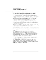
HP 1670E-Series Logic Analyzer Description
HP 1670E-Series Logic Analyzer Description
The HP 1670E-series logic analyzers are part of a family of general-
purpose logic analyzers. The HP 1670E-series consists of three models
ranging in channel width from 68 channels to 136 channels, with 100-
MHz state and 250-MHz timing speeds. The HP 1670E-series logic
analyzer are designed as full-featured standalone or network-
configurable instruments for use by digital and microprocessor
hardware and software designers. All models have HP-IB, RS-232-C,
Centronics, and Ethernet LAN interfaces for hard copy printouts and
control by a host computer.
Memory depth is 1 M per channel in all pod pair groupings, or 2 M per
channel on one pod of a pod pair in half-channel mode.
Measurement data is displayed as data listings and waveforms, and can
also be plotted on a chart or compared to a reference image. Profiled
data is displayed as histograms of activity by time, state, or address
range.
The 100-MHz state analyzer has master, master/slave, and
demultipexed clocking modes available. Measurement data can be
stamped with state or time tags. For triggering and data storage, the
state analyzer uses 12 sequence levels with two-way branching, 10
pattern resource terms, 2 range terms, and 2 timers.
The state analyzer has a separate mode for State Compare, which
allows you to quickly compare listings.
The 250-MHz timing analyzer has two timing modes with variable
width, depth, and speed selections. Sequential triggering uses 10
sequence levels with two-way branching, 8 pattern resource terms, 2
range terms, 2 edge terms and 2 timers.
Summary of Contents for 1670E Series
Page 6: ...6 In This Book...
Page 26: ...26 Contents...
Page 27: ...27 Section 1 Logic Analyzer...
Page 28: ...28...
Page 29: ...29 1 Logic Analyzer Overview...
Page 39: ...39 2 Connecting Peripherals...
Page 49: ...49 3 Using the Logic Analyzer...
Page 72: ...72 Using the Logic Analyzer The Inverse Assembler...
Page 73: ...73 4 Using the Trigger Menu...
Page 101: ...101 5 Using the Oscilloscope...
Page 151: ...151 6 Using the Pattern Generator...
Page 199: ...199 7 Triggering Examples...
Page 237: ...237 8 File Management...
Page 249: ...249 9 Logic Analyzer Reference...
Page 360: ...360 Logic Analyzer Reference The Compare Menu...
Page 361: ...361 10 System Performance Analysis SPA Software...
Page 397: ...397 11 Logic Analyzer Concepts...
Page 430: ...430 Logic Analyzer Concepts The Analyzer Hardware Oscilloscope board theory Oscilloscope board...
Page 439: ...439 12 Troubleshooting the Logic Analyzer...
Page 455: ...455 13 Specifications...
Page 471: ...471 14 Operator s Service...
Page 479: ...479 Operator s Service Troubleshooting Troubleshooting Flowchart 2...
Page 491: ...491 Section 2 LAN...
Page 492: ...492...
Page 493: ...493 15 Introducing the LAN Interface...
Page 497: ...497 16 Connecting and Configuring the LAN...
Page 506: ...506 Connecting and Configuring the LAN Connecting and Configuring the LAN...
Page 507: ...507 17 Accessing the Logic Analyzer File System Using the LAN...
Page 515: ...515 18 Using the LAN s X Window Interface...
Page 527: ...527 19 Retrieving and Restoring Data Using the LAN...
Page 539: ...539 20 Programming the Logic Analyzer Using the LAN...
Page 546: ...546 Programming the Logic Analyzer Using the LAN Programming the Logic Analyzer Using the LAN...
Page 547: ...547 21 LAN Concepts...
Page 555: ...555 22 Troubleshooting the LAN Connection...
Page 580: ...580 Troubleshooting the LAN Connection Getting Service Support...
Page 581: ...581 Section 3 Symbol Utility...
Page 582: ...582...
Page 583: ...583 23 Symbol Utility Introduction...
Page 588: ...588 Symbol Utility Introduction Symbol Utility Introduction...
Page 589: ...589 24 Getting Started with the Symbol Utility...
Page 597: ...597 25 Using the Symbol Utility...
Page 609: ...609 26 Symbol Utility Features and Functions...


