262
Logic Analyzer Reference
Probing
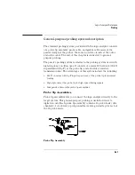
Probe and Pod Grounding
Each pod is grounded by a long, black, pod ground lead. You can
connect the ground lead directly to a ground pin on your target system
or use a grabber. To connect the ground lead to grounded pins on your
target system, you must use 0.63-mm (0.025-in) square pins, or use
round pins with a diameter of 0.66 mm (0.026 in) to 0.84 mm (0.033
in). The pod ground lead must always be used.
Each probe can be individually grounded with a short black extension
lead that connects to the probe tip socket. You can then use a grabber
or the grounded pins on your target system in the same way you
connect the data lines. For extra confidence in your measurements,
grounding every third or fourth probe is recommended.
When probing signals with rise and fall times of 1 ns or less, grounding
each probe lead with the 2-inch ground lead is recommended. In
addition, always use the probe ground on a clock probe.
Probe Leads
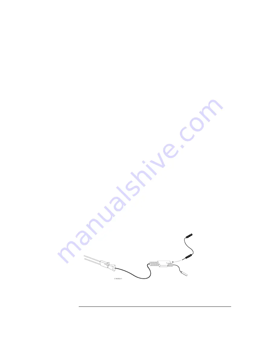
The probe leads consists of one 12-inch twisted-pair cable, one ground
tap, and one grabber. The probe lead, which connects to the target
system, has an integrated RC network with an input impedance of 100
kW in parallel with approximately 8 pF, and all in series with 250 W.
The probe lead has a two-pin connector on one end that snaps into the
probe housing.
Probe Ground Lead
Summary of Contents for 1670E Series
Page 6: ...6 In This Book...
Page 26: ...26 Contents...
Page 27: ...27 Section 1 Logic Analyzer...
Page 28: ...28...
Page 29: ...29 1 Logic Analyzer Overview...
Page 39: ...39 2 Connecting Peripherals...
Page 49: ...49 3 Using the Logic Analyzer...
Page 72: ...72 Using the Logic Analyzer The Inverse Assembler...
Page 73: ...73 4 Using the Trigger Menu...
Page 101: ...101 5 Using the Oscilloscope...
Page 151: ...151 6 Using the Pattern Generator...
Page 199: ...199 7 Triggering Examples...
Page 237: ...237 8 File Management...
Page 249: ...249 9 Logic Analyzer Reference...
Page 360: ...360 Logic Analyzer Reference The Compare Menu...
Page 361: ...361 10 System Performance Analysis SPA Software...
Page 397: ...397 11 Logic Analyzer Concepts...
Page 430: ...430 Logic Analyzer Concepts The Analyzer Hardware Oscilloscope board theory Oscilloscope board...
Page 439: ...439 12 Troubleshooting the Logic Analyzer...
Page 455: ...455 13 Specifications...
Page 471: ...471 14 Operator s Service...
Page 479: ...479 Operator s Service Troubleshooting Troubleshooting Flowchart 2...
Page 491: ...491 Section 2 LAN...
Page 492: ...492...
Page 493: ...493 15 Introducing the LAN Interface...
Page 497: ...497 16 Connecting and Configuring the LAN...
Page 506: ...506 Connecting and Configuring the LAN Connecting and Configuring the LAN...
Page 507: ...507 17 Accessing the Logic Analyzer File System Using the LAN...
Page 515: ...515 18 Using the LAN s X Window Interface...
Page 527: ...527 19 Retrieving and Restoring Data Using the LAN...
Page 539: ...539 20 Programming the Logic Analyzer Using the LAN...
Page 546: ...546 Programming the Logic Analyzer Using the LAN Programming the Logic Analyzer Using the LAN...
Page 547: ...547 21 LAN Concepts...
Page 555: ...555 22 Troubleshooting the LAN Connection...
Page 580: ...580 Troubleshooting the LAN Connection Getting Service Support...
Page 581: ...581 Section 3 Symbol Utility...
Page 582: ...582...
Page 583: ...583 23 Symbol Utility Introduction...
Page 588: ...588 Symbol Utility Introduction Symbol Utility Introduction...
Page 589: ...589 24 Getting Started with the Symbol Utility...
Page 597: ...597 25 Using the Symbol Utility...
Page 609: ...609 26 Symbol Utility Features and Functions...


