436
Logic Analyzer Concepts
The Analyzer Hardware
RAM
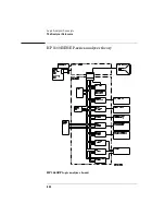
Consisting of five 256Kx16 VRAM ICs and RAM addressing circuitry,
the RAM stores the desired patterns that appear at the module output.
The RAM addressing circuitry is merely a counter which addresses the
pattern locations in RAM. When the end of the vector listing is reached,
the addressing circuitry is loaded from the loop register with the
address of the first vector of the listing to provide an uninterrupted
vector loop. The RAM output is sent to the Output Driver circuit where
the patterns are presented in a logic configuration usable by the output
pods.
Output Driver
The output driver circuit is made up of a series of latch/logic translators
and multiplexers. The latch/translators convert the working-level TTL
signals to output-level ECL signals for each channel. The ECL-level
signals are then directed to the multiplexers.
The multiplexers, one per channel, direct the programmed data
patterns to the output channels. The single-ended ECL-level signals
are converted to differential signals which are routed to the output
cables and to the pods. Note that the differential ECL output signal of
the pattern generator module is not suitable to directly drive ECL
circuitry.
Clock Circuit
The clock circuit paces the loop register, the RAM address circuitry,
and the multiplexers in the output driver according to the desired data
rate. A 200 MHz clock source is directed through a divider circuit
which provides a 100 MHz and 50 MHz clock in addition to 200 MHz.
The 200 MHz, 100 MHz, 50 MHz and external clock signals are routed
to a clock select multiplexer. The output of the multiplexer, which
represents the user-selected clocking rate, is distributed to the above
listed subcircuits.
Summary of Contents for 1670E Series
Page 6: ...6 In This Book...
Page 26: ...26 Contents...
Page 27: ...27 Section 1 Logic Analyzer...
Page 28: ...28...
Page 29: ...29 1 Logic Analyzer Overview...
Page 39: ...39 2 Connecting Peripherals...
Page 49: ...49 3 Using the Logic Analyzer...
Page 72: ...72 Using the Logic Analyzer The Inverse Assembler...
Page 73: ...73 4 Using the Trigger Menu...
Page 101: ...101 5 Using the Oscilloscope...
Page 151: ...151 6 Using the Pattern Generator...
Page 199: ...199 7 Triggering Examples...
Page 237: ...237 8 File Management...
Page 249: ...249 9 Logic Analyzer Reference...
Page 360: ...360 Logic Analyzer Reference The Compare Menu...
Page 361: ...361 10 System Performance Analysis SPA Software...
Page 397: ...397 11 Logic Analyzer Concepts...
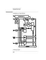
Page 430: ...430 Logic Analyzer Concepts The Analyzer Hardware Oscilloscope board theory Oscilloscope board...
Page 439: ...439 12 Troubleshooting the Logic Analyzer...
Page 455: ...455 13 Specifications...
Page 471: ...471 14 Operator s Service...
Page 479: ...479 Operator s Service Troubleshooting Troubleshooting Flowchart 2...
Page 491: ...491 Section 2 LAN...
Page 492: ...492...
Page 493: ...493 15 Introducing the LAN Interface...
Page 497: ...497 16 Connecting and Configuring the LAN...
Page 506: ...506 Connecting and Configuring the LAN Connecting and Configuring the LAN...
Page 507: ...507 17 Accessing the Logic Analyzer File System Using the LAN...
Page 515: ...515 18 Using the LAN s X Window Interface...
Page 527: ...527 19 Retrieving and Restoring Data Using the LAN...
Page 539: ...539 20 Programming the Logic Analyzer Using the LAN...
Page 546: ...546 Programming the Logic Analyzer Using the LAN Programming the Logic Analyzer Using the LAN...
Page 547: ...547 21 LAN Concepts...
Page 555: ...555 22 Troubleshooting the LAN Connection...
Page 580: ...580 Troubleshooting the LAN Connection Getting Service Support...
Page 581: ...581 Section 3 Symbol Utility...
Page 582: ...582...
Page 583: ...583 23 Symbol Utility Introduction...
Page 588: ...588 Symbol Utility Introduction Symbol Utility Introduction...
Page 589: ...589 24 Getting Started with the Symbol Utility...
Page 597: ...597 25 Using the Symbol Utility...
Page 609: ...609 26 Symbol Utility Features and Functions...

