145
Using the Oscilloscope
The Scope Auto Measure Menu
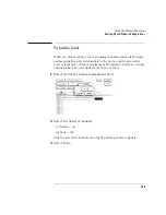
Automatic measurements display
The large field in the middle row of the menu is called the automatic
measurements display. This display shows the nine automatic
measurements and their values.
See Also
"Automatic Measurement Algorithms" at the end of this section for an
explanation of each of these fields.
Measurement setup requirements
Measurements typically should be made at the fastest possible sweep
speed in order to obtain the most accurate measurement possible. You
can only make automatic measurements with data that is currently
being displayed in the waveform display area. Keep the following in
mind when making measurements:
•
At least one full cycle of the waveform, with at least two like edges, must
be displayed for Period and Freq measurements.
•
A complete positive pulse must be displayed to make a +Width
measurement.
•
A complete negative pulse must be displayed to make a -Width
measurement.
•
The leading (rising) edge of the waveform must be displayed for Risetime,
and rising edge Preshoot and Overshoot measurements.
•
The trailing (falling) edge of the waveform must be displayed for Falltime,
and falling edge Preshoot and Overshoot measurements.
•
Risetime, Falltime, Preshoot, and Overshoot measurements will be more
accurate if you expand the edge of the waveform by selecting a faster
sweep speed.
•
If the signal is clipped, the automatic measurements cannot be made.
Summary of Contents for 1670E Series
Page 6: ...6 In This Book...
Page 26: ...26 Contents...
Page 27: ...27 Section 1 Logic Analyzer...
Page 28: ...28...
Page 29: ...29 1 Logic Analyzer Overview...
Page 39: ...39 2 Connecting Peripherals...
Page 49: ...49 3 Using the Logic Analyzer...
Page 72: ...72 Using the Logic Analyzer The Inverse Assembler...
Page 73: ...73 4 Using the Trigger Menu...
Page 101: ...101 5 Using the Oscilloscope...
Page 151: ...151 6 Using the Pattern Generator...
Page 199: ...199 7 Triggering Examples...
Page 237: ...237 8 File Management...
Page 249: ...249 9 Logic Analyzer Reference...
Page 360: ...360 Logic Analyzer Reference The Compare Menu...
Page 361: ...361 10 System Performance Analysis SPA Software...
Page 397: ...397 11 Logic Analyzer Concepts...
Page 430: ...430 Logic Analyzer Concepts The Analyzer Hardware Oscilloscope board theory Oscilloscope board...
Page 439: ...439 12 Troubleshooting the Logic Analyzer...
Page 455: ...455 13 Specifications...
Page 471: ...471 14 Operator s Service...
Page 479: ...479 Operator s Service Troubleshooting Troubleshooting Flowchart 2...
Page 491: ...491 Section 2 LAN...
Page 492: ...492...
Page 493: ...493 15 Introducing the LAN Interface...
Page 497: ...497 16 Connecting and Configuring the LAN...
Page 506: ...506 Connecting and Configuring the LAN Connecting and Configuring the LAN...
Page 507: ...507 17 Accessing the Logic Analyzer File System Using the LAN...
Page 515: ...515 18 Using the LAN s X Window Interface...
Page 527: ...527 19 Retrieving and Restoring Data Using the LAN...
Page 539: ...539 20 Programming the Logic Analyzer Using the LAN...
Page 546: ...546 Programming the Logic Analyzer Using the LAN Programming the Logic Analyzer Using the LAN...
Page 547: ...547 21 LAN Concepts...
Page 555: ...555 22 Troubleshooting the LAN Connection...
Page 580: ...580 Troubleshooting the LAN Connection Getting Service Support...
Page 581: ...581 Section 3 Symbol Utility...
Page 582: ...582...
Page 583: ...583 23 Symbol Utility Introduction...
Page 588: ...588 Symbol Utility Introduction Symbol Utility Introduction...
Page 589: ...589 24 Getting Started with the Symbol Utility...
Page 597: ...597 25 Using the Symbol Utility...
Page 609: ...609 26 Symbol Utility Features and Functions...


