193
Using the Pattern Generator
ASCII File Commands
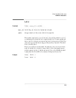
No data is allowed in the same line as the VECTor command. The line
termination in the VECTor command line is included in the character
count for the file.
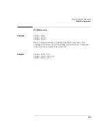
The <char_count> field is not required as part of the VECTor command
when creating a disk file, and will be ignored if included.
Example
VECTor #800010457
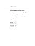
Vector Data
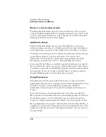
The data portion of the ASCII file is basically an array of hexadecimal
data fields. Each row of the array corresponds to a single line of the
main program. Each column of the array corresponds to a single label
as defined on the format menu.
Data fields are separated by one or more blank characters. A line
termination (carriage return or carriage line feed) signals the
end of a line and the start of a new line. If a data field has more data
than the label width would indicate, only the least significant bits of the
data field are used. If there are more data fields in a row than there are
labels, the extra data fields (last data fields in the row) are ignored. If
there are fewer data fields in a row than there are labels, the data for
the extra (right-most) labels will be zero.
Data lines consisting of only line termination characters are ignored.
The MAIN SEQUENCE must have at least two data lines. In the ASCII
data file, a row consisting of only ’*M’ is used to signal the start of the
main sequence. If there is to be no data in the init sequence, the first
row of the file after the VECTor command must be ’*M’. Note that the
quotes in ’*M’ are not really in the file. The line termination after the
’*M’ (as well as the ’*M’) must be included in the character count for a
file loaded using a remote bus.
Summary of Contents for 1670E Series
Page 6: ...6 In This Book...
Page 26: ...26 Contents...
Page 27: ...27 Section 1 Logic Analyzer...
Page 28: ...28...
Page 29: ...29 1 Logic Analyzer Overview...
Page 39: ...39 2 Connecting Peripherals...
Page 49: ...49 3 Using the Logic Analyzer...
Page 72: ...72 Using the Logic Analyzer The Inverse Assembler...
Page 73: ...73 4 Using the Trigger Menu...
Page 101: ...101 5 Using the Oscilloscope...
Page 151: ...151 6 Using the Pattern Generator...
Page 199: ...199 7 Triggering Examples...
Page 237: ...237 8 File Management...
Page 249: ...249 9 Logic Analyzer Reference...
Page 360: ...360 Logic Analyzer Reference The Compare Menu...
Page 361: ...361 10 System Performance Analysis SPA Software...
Page 397: ...397 11 Logic Analyzer Concepts...
Page 430: ...430 Logic Analyzer Concepts The Analyzer Hardware Oscilloscope board theory Oscilloscope board...
Page 439: ...439 12 Troubleshooting the Logic Analyzer...
Page 455: ...455 13 Specifications...
Page 471: ...471 14 Operator s Service...
Page 479: ...479 Operator s Service Troubleshooting Troubleshooting Flowchart 2...
Page 491: ...491 Section 2 LAN...
Page 492: ...492...
Page 493: ...493 15 Introducing the LAN Interface...
Page 497: ...497 16 Connecting and Configuring the LAN...
Page 506: ...506 Connecting and Configuring the LAN Connecting and Configuring the LAN...
Page 507: ...507 17 Accessing the Logic Analyzer File System Using the LAN...
Page 515: ...515 18 Using the LAN s X Window Interface...
Page 527: ...527 19 Retrieving and Restoring Data Using the LAN...
Page 539: ...539 20 Programming the Logic Analyzer Using the LAN...
Page 546: ...546 Programming the Logic Analyzer Using the LAN Programming the Logic Analyzer Using the LAN...
Page 547: ...547 21 LAN Concepts...
Page 555: ...555 22 Troubleshooting the LAN Connection...
Page 580: ...580 Troubleshooting the LAN Connection Getting Service Support...
Page 581: ...581 Section 3 Symbol Utility...
Page 582: ...582...
Page 583: ...583 23 Symbol Utility Introduction...
Page 588: ...588 Symbol Utility Introduction Symbol Utility Introduction...
Page 589: ...589 24 Getting Started with the Symbol Utility...
Page 597: ...597 25 Using the Symbol Utility...
Page 609: ...609 26 Symbol Utility Features and Functions...

