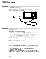
Self Cal menu calibrations
Messages will be displayed as each calibration routine is completed to indicate calibration has
passed or failed. The resulting calibration factors are automatically stored to nonvolatile RAM
at the conclusion of each calibration routine.
The Self Cal menu lets you optimize vertical sensitivity (Vert Cal) for channels 1 and 2
individually or both channels on a board simultaneously. Also, the Self Cal menu lets you
optimize delay (Delay) for channel 1 and 2 separately, then Time Null for channel 2 and the
Logic Trigger.
1
Optimize Vert Cal of the Self Cal.
a
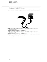
Connect two BNC 50-
Ω
, 9-inch cables to the BNC tee adapter. Connect the BNC 50
Ω
(f)(f) adapter to the BNC tee adapter, and connect the 48-inch BNC cable to the BNC
50
Ω
(f)(f) adapter. Once you select Start, the instrument will prompt you to connect
the cables to the appropriate locations on the rear panel of the instrument.
b
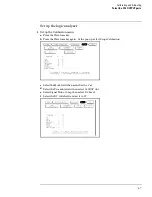
Select the Mode field, then select Self Cal from the pop-up menu.
c
Select the Procedure field, then select Vert Cal from the pop-up menu.
d
Select the Channel field, then select a channel choice from the pop-up menu.
e
Select the Start field and follow the instructions on the display.
f
After completion of Vertical Calibration, remove the cables from the instrument.
2
Optimize Delay of the Self Cal.
a
Obtain a BNC 50-
Ω
, 48-inch cable. Once you select Start, the instrument will prompt
you to connect the cable to the appropriate location on the rear panel of the
instrument.
b
Select the Procedure field, then select Delay from the pop-up menu.
c
Select the Channel field, then select C1.
d
Select the Start field and follow the instructions on the display.
e
Repeat steps c and d for channel 2.
f
After completing all of the channel delay calibrations, remove the cable from the
oscilloscope.
3
Optimize the Time Null of the Self Cal.
a
Connect two BNC 50-
Ω
, 9-inch cables to the BNC tee adapter. Connect the BNC 50
Ω
(f)(f) adapter to the BNC tee adapter, and connect the 48-inch BNC cable to the BNC
50
Ω
(f)(f) adapter. Once you select Start, the instrument will prompt you to connect
the cables to the appropriate locations on the rear panel of the instrument.
b
Select the Procedure field, then select Time Null from the pop-up menu.
c
Select the Start field and follow the instructions on the display.
d
After completion of the Time Null calibration, remove the cables from the instrument.
4
Calibrate the Logic Trigger of the Self Cal.
a
Obtain a BNC 50-
Ω
, 48-inch cable.
b
Select Start. The instrument will prompt you to connect the cable to the appropriate
location on the rear panel of the instrument.
c
Select the Procedure field, then select Logic Trigger from the pop-up menu.
d
Select the Start field and follow the instructions on the display.
e
After completion of the Logic Trigger calibration, remove the cable from the
instrument.
Calibrating and Adjusting
To calibrate the oscilloscope
4–5
Summary of Contents for 1670G Series
Page 20: ...1 12...
Page 116: ...Testing Performance Performance Test Record pattern generator 3 92...
Page 126: ...Calibrating and Adjusting To test the CAL OUTPUT ports 4 10...
Page 166: ...Exploded View of the Agilent 1670G series logic analyzer Replacing Assemblies 6 4...
Page 201: ...Theory of Operation The Oscilloscope Board 8 11...


