background image

To remove and replace the CPU board

1

Using previous procedures, remove the following assemblies:

Handle

Rear Feet

Cover

Disk Drive Assembly

Acquisition Board

2

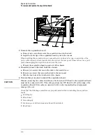
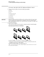
Disconnect the following cables from the CPU board:

C A U T I O N

When reconnecting the cables, the ribbon cable from the CPU Board to the Acquisition Board
must not be connected to J12.  This cable goes from the CPU Board to J13 (at the edge of the
Acquisition Board). If the cable is connected to J12 on the Acquisition Board equipment
damage will occur.

Rear Panel (J5)

LCD Data (J4)

Removing the LCD data cable from the CPU board

LCD Inverter (J3)

GPIB (J13)

RS-232 (J8)

Front Panel (J7)

3

Slide the board out the side of the instrument.

4

Reverse this procedure to install the CPU board.

When connecting the LCD data cable to the CPU board, ensure the blue side of the
cable faces away from the SIMM memory.

C A U T I O N

When reconnecting the  cables, the ribbon cable from the CPU Board to the Acquisition
Board must not be connected to J12.  This cable goes from the CPU Board to J13 (at the edge
of the Acquisition Board). If the cable is connected to J12 on the Acquisition Board
equipment damage will occur.

Check that the following assemblies are properly installed before installing the CPU board:

Replacing Assemblies

To remove and replace the CPU board

6–9

Summary of Contents for 1670G Series

Page 1: ...1670 97023 November 2003 For Safety information Warranties and Regulatory information see the pages at the end of the book Copyright Agilent Technologies 1987 2003 All Rights Reserved Agilent Technolo...

Page 2: ...nels in the Agilent 1672G 32 data channels and 2 clock data channels in the Agilent 1673G 3 5 inch flexible disk drive 2 GB hard disk drive GPIB RS 232 C Centronics and LAN interfaces Thinlan and Ethe...

Page 3: ...ime between markers Lightweight mini probes Service Strategy The service strategy for this instrument is the replacement of defective assemblies This service guide contains information for finding a d...

Page 4: ...for use Chapter 3 gives instructions on how to test the performance of the logic analyzer Chapter 4 contains calibration instructions for the logic analyzer Chapter 5 contains self tests and flowchart...

Page 5: ...alyzer 2 4 3 Testing Performance To perform the self tests 3 3 To make the test connectors logic analyzer 3 7 To test the threshold accuracy logic analyzer 3 9 Set up the equipment 3 9 Set up the logi...

Page 6: ...3 59 Set up the logic analyzer 3 60 Connect the logic analyzer 3 61 Acquire the data 3 62 Perform an operational accuracy calibration 3 62 To test the voltage measurement accuracy oscilloscope 3 63 Se...

Page 7: ...the logic analyzer 4 7 Verify the DC CAL OUTPUT port 4 8 Set up the logic analyzer 4 9 Verify the AC CAL OUTPUT port 4 9 5 Troubleshooting To use the flowcharts 5 2 To check the power up tests 5 11 To...

Page 8: ...To remove and replace the fan 6 18 To remove and replace the pattern generator cables pattern generator option only 6 18 To remove and replace the GPIB and RS 232 C cables 6 19 To remove and replace...

Page 9: ...ions pattern generator 1 4 Characteristics logic analyzer 1 5 Characteristics oscilloscope 1 5 Characteristics pattern generator 1 6 Recommended Test Equipment logic analyzer 1 9 Recommended Test Equi...

Page 10: ...ables 01660 61605 Note 2 Grabbers 20 per pack 5090 4356 Note 1 Probe ground 5 per pack 5959 9334 Note 1 Double Probe Adapter 16542 61607 1 PS2 Mouse C3751 60201 1 Note 1 Quantities 8 1670G 6 1671G 4 1...

Page 11: ...old setting Setup Hold Time Single Clock Single Edge 3 0 0 0 ns through 0 5 3 5 ns adjustable in 500 ps increments Single Clock Multiple Edges 3 5 0 0 ns through 0 5 4 0 ns adjustable in 500 ps increm...

Page 12: ...1 Specifications valid within 10 C of auto calibration temperature excluding bandwidth see note 1 for bandwidth specification 1 Upper bandwidth reduces by 2 5 MHz for every degree C above 35 C 2 Spec...

Page 13: ...scope The Agilent 1670G Logic Analyzers with an oscilloscope also include the following characteristics Maximum Sample Rate 2 Gigasample per second Number of Channels 2 Rise Time 1 700 ps ADC 8 bit re...

Page 14: ...lock outputs Synchronized to output data delay of 11 ns in 9 steps clock pod Clock input DC to 200 MHz clock pod Internal clock period Programmable from 5 ns to 250 s in a 1 2 2 5 4 5 8 sequence Exter...

Page 15: ...0 C to 40 C 50 F to 104 F Humidity Instrument probe lead sets and cables up to 80 relative humidity at 40 C 122 F Altitude To 3067 m 10 000 ft Vibration Operating Random vibration 5 to 500 Hz 10 minut...

Page 16: ...ISM Group1 Class A equipment IEC 555 2 and IEC 555 3 Immunity EN50082 1 Code1 Notes2 IEC 801 2 ESD 4kV CD 8kV AD 1 IEC 801 3 Rad 3V m 1 IEC 801 4 EFT 1kV 1 1 Performance Codes 1 PASS Normal operation...

Page 17: ...Tee BNC m f f 1250 0781 P Cable BNC m m 48 inch 8120 1840 P T SMA Coax Cable Qty 3 18 GHz bandwidth 8120 4948 P Adapter Qty 4 SMA m BNC f 1250 1200 P T Adapter SMA f BNC m 1250 2015 P Coupler Qty 4 B...

Page 18: ...measurement better than 0 25 accuracy 3458A P Power Meter Sensor 1 250 MHz 3 accuracy 436 8482A P Power Splitter Outputs differ by 0 15 dB 11667B P Blocking Capacitor BNC m f 0 18 F 200 V 10240B P BN...

Page 19: ...quipment Critical Specifications Recommended Model Part Use Oscilloscope 500 MHz Bandwidth 54820A T Probe 500 MHz Bandwidth 1160A T Output Data Pod no substitute 10460A series T T Troubleshooting Gene...

Page 20: ...1 12...

Page 21: ...2 To inspect the logic analyzer 2 2 To apply power 2 3 To operate the user interface 2 3 To clean the logic analyzer 2 3 To test the logic analyzer 2 4 Preparing for Use...

Page 22: ...on Storage Store or ship the logic analyzer in environments within the following limits Temperature 40 C to 75 C Humidity Up to 90 at 65 C Altitude Up to 15 300 meters 50 000 feet Protect the logic an...

Page 23: ...ption numbers of available power cables and plug configurations 3 Turn on the instrument power switch located on the front panel To operate the user interface To select a field on the logic analyzer s...

Page 24: ...the beginning of chapter 3 Testing Performance If you require a test to initially accept the operation perform the self tests in chapter 3 If the logic analyzer does not operate correctly go to the b...

Page 25: ...41 To test the time interval accuracy logic analyzer 3 53 To test the CAL OUTPUT ports oscilloscope 3 59 To test the input resistance oscilloscope 3 63 To test the voltage measurement accuracy oscill...

Page 26: ...riate pods showing on the screen With the oscilloscope option ensure that the operational accuracy calibration has been done before doing the performance verification tests see chapter 4 The performan...

Page 27: ...ere is a pattern generator test These procedures assume the files on the PV disk have been copied to the SYSTEM subdirectory on the hard disk drive If they have not already been copied insert the PV d...

Page 28: ...play Test remain UNTESTED 7 Select the Front Panel Test A screen duplicating the front panel appears on the screen a Press each key on the front panel The corresponding key on the screen will change f...

Page 29: ...s at one time by selecting All Tests To see more details about each test when troubleshooting failures you can run each test individually This example shows how to run all tests at once When the tests...

Page 30: ...ests You can run all tests at one time except for the Data Input Inspection by running All Tests To see more details about each test when troubleshooting failures you can run each test individually 15...

Page 31: ...of Berg strip a Solder a jumper wire to all pins on one side of the Berg strip b Solder a jumper wire to all pins on the other side of the Berg strip c Solder two resistors to the Berg strip one at e...

Page 32: ...e Berg strip b Solder a jumper wire to all pins on the other side of the Berg strip c Solder the center of the BNC connector to the center pin of one row on the Berg strip d Solder the ground tab of t...

Page 33: ...nd of this chapter Equipment Required Equipment Critical Specifications Recommended Model Part Digital Multimeter 0 1 mV resolution 0 005 accuracy 3458A Function Generator Accuracy 5 10 6 frequency DC...

Page 34: ...ECL in the pop up menu c Move the cursor over the Pod A1 channel selection field Press the Clear Entry button until all channels are assigned all then press Done d Move the cursor over the Data on Cl...

Page 35: ...cursor to the pod channel selection field then press Select In the pop up menu select Delete All then select Continue c Again press Select At the pop up menu select Insert then select Bus1 then selec...

Page 36: ...nnect the data and clock channels of pod 1 to one side of the BNC Tee 2 Using a BNC banana cable connect the voltmeter to the other side of the BNC Tee 3 Connect the BNC Tee to the Main Signal output...

Page 37: ...d to the right of Pod A1 then select ECL in the pop up menu 2 Test the high to low transition a On the DC power source enter 1 438 V b On the logic analyzer press Run The display should show all chann...

Page 38: ...enter 1 162 V b On the logic analyzer press Run The display should show all channels at a logic 1 4 Record a PASS FAIL in the performance test record for Threshold Accuracy Pod 1 ECL Testing Performan...

Page 39: ...ower source enter 0 099 V b On the logic analyzer press Run The display should show all channels at a logic 0 3 Test the low to high transition a On the DC source enter 0 099 V b On the logic analyzer...

Page 40: ...ss the Format key b Move the cursor over the channel assignment field for the pod tested Press Clear Entry until all channels show unassigned all c Move the cursor over the Data on Clocks channel assi...

Page 41: ...003 Digitizing Oscilloscope 6 GHz bandwidth 58 ps rise time 54750A w 54751A Adapter SMA m BNC f 1250 1200 SMA Coax Cable Qty 3 18 GHz bandwidth 8120 4948 Coupler BNC m m 1250 0216 BNC Test Connector...

Page 42: ...V div Offset 1 300 V Alternate Scale Attenuation 20 00 1 Scale 200 mV div Offset 1 300 V Thresholds user defined Units Volts Upper 980 mV Middle 1 30 V Lower 1 62 V Set up the logic analyzer 1 Set up...

Page 43: ...nu Select Done to exit the menu c Select Acquisition Control If the Acquisition Control is Manual use the cursor keys to move the cursor to the Acquisition Mode field Press the Select key to toggle th...

Page 44: ...er Output Connect the Agilent 1670G or Agilent 1671G Logic Analyzer to the Pulse Generator Testing Combinations Connect to 8133A Channel 2 Output Connect to 8133A Channel 2 Output Connect to 8133A Cha...

Page 45: ...te the data channels that are connected according to one of the previous tables a Press the Format key b Select the field showing the channel assignments for one of the pods being tested then press th...

Page 46: ...l Bus1 Type the following for your logic analyzer then press the Select key Agilent 1670G AA Agilent 1672G AA Agilent 1671G 2A Agilent 1673G 0A 5 5 Enable the pulse generator channel 1 channel 2 and t...

Page 47: ...Timebase menu increase Position 6 666 ns If the period is not less than 6 666 ns decrease the pulse generator Period in 10 ps increments until one of the two periods measured is less than 6 666 ns 2...

Page 48: ...e setup hold combinations 2 Disable the pulse generator channel 1 COMP with the LED off 3 Using the Delay mode of the pulse generator channel 1 position the pulses according to the setup time of the s...

Page 49: ...re the period from falling edge to falling edge which is not a valid measurement 4 Select the clock to be tested a In the Master Clock menu select the clock field to be tested then select the clock ed...

Page 50: ...Difference Listing 6 Press the blue shift key then press the Run key If the analyzer obtains two to four acquisitions without the Stop Condition Satisfied message appearing then the test passes Press...

Page 51: ...ted then select the clock edge as indicated in the table The first time through this test use the top clock and edge Clocks J K L M b Connect the clock to be tested to the pulse generator channel 1 ou...

Page 52: ...13 for the next setup hold combination listed in step 1 on page 3 24 until all listed setup hold combinations have been tested When aligning the data and clock waveforms using the oscilloscope align...

Page 53: ...003 Digitizing Oscilloscope 6 GHz bandwidth 58 ps rise time 54750A w 54751A Adapter SMA m BNC f 1250 1200 SMA Coax Cable Qty 3 18 GHz bandwidth 8120 4948 Coupler BNC m m 1250 0216 BNC Test Connector 6...

Page 54: ...0 1 Scale 200 mV div Offset 1 300 V Alternate Scale Attenuation 20 00 1 Scale 200 mV div Offset 1 300 V Thresholds user defined Units Volts Upper 980 mV Middle 1 30 V Lower 1 62 V Set up the logic ana...

Page 55: ...e pop up menu Select Done to exit the menu c Select Acquisition Control If the Acquisition Control is Manual use the cursor keys to move the cursor to the Acquisition Mode field Press the Select key t...

Page 56: ...or Agilent 1671G Logic Analyzer to the Pulse Generator Testing Combinations Connect to 8133A Channel 2 Output Connect to 8133A Channel 2 Output Connect to 8133A Channel 1 Output 1 Pod 1 channel 3 Pod...

Page 57: ...only 3 Activate the data channels that are connected according to one of the previous tables a Press the Format key b Select the field showing the channel assignments for one of the pods being tested...

Page 58: ...under the label Bus1 Type the following for your logic analyzer then press Select Agilent 1670G AA Agilent 1672G AA Agilent 1671G 2A Agilent 1673G A 5 Enable the pulse generator channel 1 channel 2 a...

Page 59: ...imebase menu increase Position 6 666 ns If the period is not less than 6 666 ns decrease the pulse generator Period in 10 ps increments until one of the two periods measured is less than 6 666 ns 2 Ch...

Page 60: ...ns d Select Done to exit the setup hold combinations 2 Disable the pulse generator channel 1 COMP with the LED off 3 Using the Delay mode of the pulse generator channel 1 position the pulses according...

Page 61: ...lue The settings provided in this procedure measure the period from falling edge to falling edge which is not a valid measurement 4 Select the clocks to be tested a Select the clock field to be tested...

Page 62: ...elect Execute d Move the cursor to Specify Stop Measurement and press the Select key Press Select again to turn on Compare At the pop up menu select Compare Move the cursor to the Equal field and pres...

Page 63: ...1 Delay until the pulses are aligned according the the setup time of the setup hold combination selected 0 0 ps or 100 ps Disregard the oscilloscope Period 2 value The settings provided in this proced...

Page 64: ...ination a In the logic analyzer Format menu select Master Clock b Turn off and disconnect the clocks just tested c Repeat steps 1 through 12 for the next setup hold combination listed in step 1 on pag...

Page 65: ...ulse Generator 150 MHz 3 0 ns pulse width 600 ps rise time 8133A option 003 Digitizing Oscilloscope 6 GHz bandwidth 58 ps rise time 54750A w 54751A Adapter SMA m BNC f 1250 1200 SMA Coax Cable Qty 3 1...

Page 66: ...200 mV div Offset 1 300 V Alternate Scale Attenuation 20 00 1 Scale 200 mV div Offset 1 300 V Thresholds user defined Units Volts Upper 980 mV Middle 1 30 V Lower 1 62 V Set up the logic analyzer Do t...

Page 67: ...then select Time in the pop up menu Select Done to exit the menu c Select Acquisition Control If the Acquisition Control is Manual use the cursor keys to move the cursor to the Acquisition Mode field...

Page 68: ...or Connect the Agilent 1670G or Agilent 1671G Logic Analyzer to the Pulse Generator Testing Combinations Connect to 8133A Channel 2 Output Connect to 8133A Channel 2 Output Connect to 8133A Channel 1...

Page 69: ...he data channels that are connected according to one of the previous tables a Press the Format key b Select the field showing the channel assignments for one of the pods being tested Press the Clear e...

Page 70: ...l Bus1 Type the following for your logic analyzer then press the Select key Agilent 1670G AA Agilent 1672G AA Agilent 1671G 2A Agilent 1673G A 5 Enable the pulse generator channel 1 channel 2 and trig...

Page 71: ...nnel 2 then select Enter to display the master to master clock time width 2 If the positive going pulse width is more than 6 666 ns go to step d If the positive going pulse width is less than or equal...

Page 72: ...he oscilloscope knob position the data waveform so that the waveform is centered on the screen c On the oscilloscope select Shift width channel 1 then select Enter to display the data signal pulse wid...

Page 73: ...any multiple clock edge c Select the Setup Hold field then select the setup hold to be tested for all pods The first time through this test use the top combination in the following table Setup Hold C...

Page 74: ...annel 1 then select Enter to display the setup time Time 1 2 d Adjust the pulse generator channel 2 Delay until the pulses are aligned according the the setup time of the setup hold combination select...

Page 75: ...ain to turn on Compare At the pop up menu select Compare Move the cursor to the Equal field and press the Select key At the pop up menu select Not Equal Press Done e Move the cursor to the Reference L...

Page 76: ...ed When aligning the data and clock waveforms using the oscilloscope align the waveforms according to the setup time of the setup hold combination being tested 0 0 ps or 100 ps Test the next channels...

Page 77: ...pulse width 600 ps rise time 8133A Option 003 Function Generator Accuracy 5 10 6 frequency 3325B Option 002 SMA Cable 8120 4948 Adapter BNC m SMA f 1250 2015 BNC Test Connector 6x2 Set up the equipme...

Page 78: ...onnect the logic analyzer 1 Using a 6 by 2 test connector connect channel 0 of Pod A1 to the pulse generator channel 1 output 2 Using the SMA cable and the BNC adapter connect the External Input of th...

Page 79: ...e Config key b In the Configuration menu assign Pod 1 to Machine 1 To assign Pod 1 select the Pod 1 field then select Machine 1 c In the Analyzer 1 box select the Type field then select Timing Testing...

Page 80: ...key to put an asterisk in the channel position activating the channel then press the Done key 3 Set up the Trigger menu a Select Acquisition Control Select the Acquisition Mode field and the acquisit...

Page 81: ...dial in 100 ns d Select the Markers Off field then select Pattern e Select the Specify Patterns field Select X entering 1 and O entering 1 f Select Done to exit the Specify Patterns menu g Move the c...

Page 82: ...logic analyzer to acquire data for at least 1 minute Observe the X to O time field and ensure the X marker to O marker time is between 409 56 and 409 64 s during the test Record the results in the per...

Page 83: ...ecommended Model Part Digital Multimeter Measure resistance 4 wire better than 0 25 accuracy 3458A Cables 2 BNC m m 48 inch 8120 1840 Adapter BNC Tee m f f 1250 0781 Adapters 2 BNC f to Dual Banana Pl...

Page 84: ...knob to dial in 1 1 e Move the cursor to the V Div field then use the RPG knob to dial in 20 mV f Move the cursor to the Offset field Set the Offset to 0 V by typing 0 then pressing the Select key g...

Page 85: ...each BNC cable to the 4 wire resistance connections on the multimeter and connect the free ends of the cables to the BNC Tee Connect the male end of the BNC tee to the channel 1 input of the oscillos...

Page 86: ...ield to 50 DC and V Div to 1 V Div Repeat steps 1 through 3 6 In the Channel menu change the Coupling field to 50 DC and V Div to 4 V Div Repeat steps 1 through 3 7 Connect the male end of the BNC tee...

Page 87: ...ired Equipment Critical Specifications Recommended Model Part DC Power Supply 14 Vdc to 14 Vdc 0 1 mV resolution 3245A option 002 Digital Multimeter Better than 0 1 accuracy 3458A Cable BNC m m 48 inc...

Page 88: ...e the cursor to the s Div field then use the RPG knob to dial in 500 ns 2 Set up the Display menu a Press the Display key b Select the Mode field then select Average c Move the cursor to the Average f...

Page 89: ...Off by moving the cursor to the T markers field and pressing Select Select Off Connect the logic analyzer 1 Using a BNC to banana adapter connect one end of the cable to the power supply Connect the B...

Page 90: ...t the power supply from the channel input b Press the blue shift key then press the Run key Wait for approximately five seconds averaging complete then press Stop c Press the Markers key Move the curs...

Page 91: ...35 000 Vdc 1 mV resolution 3245A option 002 Digital Multimeter Better than 0 1 accuracy 3458A Cable BNC m m 48 inch 8120 1840 Adapter cable to power supply BNC f to Dual Banana Plug 1251 2277 Adapter...

Page 92: ...ressing the Select key f Select the Coupling field then select 1M DC C AU TI O N Set the Channel Coupling field to 1M DC or damage to the equipment will result g Move the cursor to the s Div field the...

Page 93: ...rkers are On turn the V markers Off by moving the cursor to the V markers field and pressing Select Connect the logic analyzer 1 Using a BNC to banana adapter connect one end of the cable to the power...

Page 94: ...ess the Stop key Read the voltage from the Markers voltage field 0 00 V 80 mV and enter the value in the performance test record 5 Use the RPG knob to dial in 100 mV Div Press the blue shift key then...

Page 95: ...value shown on the first line of the table b Move the cursor to the Offset field Use the front panel keyboard to type in the offset value shown in the first line of the table Use the left and right cu...

Page 96: ...ons Recommended Model Part Signal Generator 1 250 MHz at approximately 170 mV rms 8656B Power Meter Sensor 1 250 MHz 3 accuracy 436 8482A Power Splitter Outputs differ by 0 15 dB 11667B Cable Type N m...

Page 97: ...Move the cursor to the Offset field Set the offset to 0 by typing 0 then pressing the Select key f Select the Coupling field then select 50 DC g Move the cursor to the s Div field press Select then us...

Page 98: ...level to 0 by typing 0 in the front panel keyboard then pressing Select 4 Turn off the voltage and time markers a Press the Marker key b Move the cursor to the V Markers field and press Select The Se...

Page 99: ...o the power splitter input Connect the power sensor to one output of the power splitter 2 Using the N to BNC adapter and the BNC cable connect the other power splitter output to the channel 1 input of...

Page 100: ...dial in a s Div value of 1 ns Div b Press the blue shift key then press the Run key After approximately 15 seconds averaging complete press the Stop key c Note the voltage reading in the Vp p field V...

Page 101: ...ment Critical Specifications Recommended Model Part Signal Generator 200 MHz timebase accuracy 0 25 ppm 8656B Opt 001 Cable BNC m m 48 inch 8120 1840 Adapter Type N m to BNC f 1250 0780 Set up the equ...

Page 102: ...Move the cursor to the Offset field Set the offset to 0 by typing 0 then pressing the Select key f Select the Coupling field then select 50 DC g Move the cursor to the s Div field press Select then u...

Page 103: ...t it to Positive 4 Set up the Markers menu a Press the Marker key b Move the cursor to the T Markers field and press Select At the pop up menu select Auto c Select the X marker and set it on C1 at Lev...

Page 104: ...up the T Markers Auto menu b Select the X marker Set On field At the pop up menu select Manual c Move the cursor to the O marker Occur field Press the 1 key then press Select d Press Done e Press the...

Page 105: ...0 MHz 0 125 x full scale 0 5 division Equipment Required Equipment Critical Specifications Recommended Model Part Signal Generator 50 MHz and 225 MHz 30 80 mV RMS output 8656B Opt 001 Cable BNC 48 inc...

Page 106: ...0 by typing 0 then pressing the Select key f Move the cursor to the Coupling field then press Select Select 50 DC g Move the cursor to the s Div field press Select then use the RPG knob to dial in 5 0...

Page 107: ...el to 0 by typing 0 in the front panel keyboard then pressing Select 4 Turn off the voltage and time markers a Press the Marker key b Move the cursor to the V Markers field and press Select The Select...

Page 108: ...lt the acquisition Read the Vp p field and record the voltage in the performance test record 2 Test the lower bandwidth trigger sensitivity a Use the RPG knob to dial in s Div of 20 ns b Set the signa...

Page 109: ...100 mV 3 of threshold setting Pod 1 ECL 139 mV 0 V 100 mV Pass Fail Pass Fail ________ ________ Pod 2 ECL 139 mV 0 V 100 mV Pass Fail Pass Fail ________ ________ Pod 3 ECL 139 mV 0 V 100 mV Pass Fail...

Page 110: ...K L M ________ ________ ________ ________ J K L M ________ ________ ________ ________ Setup Hold Time 0 5 3 5 ns J K L M ________ ________ ________ ________ J K L M ________ ________ ________ _______...

Page 111: ..._______ _______ _______ _______ Setup Hold Time 0 5 4 0 ns J K L M _______ _______ _______ _______ All Pods Channel 11 Setup Hold Time 3 5 0 0 ns J K L M _______ _______ _______ _______ Setup Hold Ti...

Page 112: ...0 20 mV Div 1 M 20 mV Div 50 200 mV Div 1 M 200 mV Div 50 1 V Div 1 M 1 V Div 50 4 V Div 1 M 4 V Div 50 20 mV Div 1 M 20 mV Div 50 200 mV Div 1 M 200 mV Div 50 1 V Div 1 M 1 V Div 50 4 V Div 1 M 4 V D...

Page 113: ...l 1 Channel 2 Channel 1 Channel 2 Zero input offset 4 V Div 1 V Div 100 mV Div 10 mV Div 4 V Div 1 V Div 100 mV Div 10 mV Div DC input offset 35 00 V 10 00 V 2 00 V 2 00 V 10 00 V 35 00 V 35 00 V 10 0...

Page 114: ...O MEAN X O MIN X O MEAN X O MIN X O MAX X O MAX X O MEAN X O ________ ________ ________ ________ ________ ________ ________ ________ ________ ________ Trigger Sensitivity Channel 1 Channel 2 Trigger...

Page 115: ...erformance Test Record pattern generator Performance Test Record pattern generator Test Settings Results Self Tests Pass Fail ________ Testing Performance Performance Test Record pattern generator 3 9...

Page 116: ...Testing Performance Performance Test Record pattern generator 3 92...

Page 117: ...4 Logic analyzer calibration 4 2 To calibrate the oscilloscope 4 3 Set up the equipment 4 3 Load the Default Calibration Factors 4 4 Self Cal menu calibrations 4 5 Calibrating and Adjusting...

Page 118: ...nce The oscilloscope circuitry in the Agilent 1670G series Logic Analyzers with the oscilloscope option requires an operational accuracy calibration by the user or service department under any of the...

Page 119: ...cation Recommended Model Part Qty Cable 2 BNC 9 inch equal length 10502A 1 Cable BNC 10503A Adapter BNC tee m f f 1250 0781 1 Adapter BNC f f ug 914 u 1250 0080 Set up the equipment Turn on the logic...

Page 120: ...Press the System key Select System then select Scope 2 Select the menu field top row second from the left then select Scope Calibration from the pop up menu 3 Select the Mode field then select Servic...

Page 121: ...ou select Start the instrument will prompt you to connect the cable to the appropriate location on the rear panel of the instrument b Select the Procedure field then select Delay from the pop up menu...

Page 122: ...provide accurate calibration for the oscilloscope operational accuracy calibration and probe calibration Equipment Required Equipment Critical Specifications Recommended Model Part Digital Multimeter...

Page 123: ...key again At the pop up select Scope Calibration c Select the Mode field then select Service Cal d Select the Procedure field then select Cal BNC Out e Select Signal Probe Comp then select DC Level f...

Page 124: ...g to four decimal places V1 _______ 3 In the Calibration menu set the DC Volts to 5 V 4 The digital voltmeter should read close to 5 0000 V Record the reading to four decimal places V2 _______ 5 In th...

Page 125: ...field press Select then use the RPG knob to dial in 1 1 Verify the AC CAL OUTPUT port 1 Using the BNC cable connect channel 1 of the oscilloscope to the AC CAL OUTPUT connector 2 In the Calibration me...

Page 126: ...Calibrating and Adjusting To test the CAL OUTPUT ports 4 10...

Page 127: ...CD display signals 5 27 To test the keyboard signals 5 28 To test the flexible disk drive voltages 5 30 To test the hard disk drive voltages 5 32 To perform the BNC test 5 34 To test the logic analyze...

Page 128: ...ive assemblies This instrument can be returned to Agilent Technologies for all service work including troubleshooting Contact your nearest Agilent Technologies Sales Office for more details C AU TI O...

Page 129: ...the PV procedure in Chapter 5 Do a Test All Refer to the PV procedures in Chapter 5 Do all self tests pass Exit the test system Is the user problem still present E N D Replace failed assembly accordi...

Page 130: ...CPU Board in the instrument Replace LCD Monitor Is the power suply fan running Ensure the power cord is properly connected Is the power cord properly connected Reconnect the power cord Suspect the pow...

Page 131: ...t Install flexible disk with operating system into flexible disk drive Apply power Reflash boot ROM with latest op sys version Turn off the instrument Apply power Does instrument finish booting Replac...

Page 132: ...Perform front panel keyboard self test Check signal input to keyboard Input signals OK Keyboard cable continuity OK Replace keyboard assembly Replace CPU board assembly CHART 4 CHART 1 Yes No No Yes...

Page 133: ...CHART 5 PV Test Is the oscilloscope option installed Is the pattern generator option installed Do all Pattern Generator Tests pass Replace acquisition board Replace pattern generator board Failure of...

Page 134: ...1 Chart 6 Problem with pattern generator Possible problem with cabling Do the cable test in Chapter 5 on suspect pod Contact HP for more information 6a 6b Does cable test pass Does cable test pass The...

Page 135: ...lloscope acquisition Replace oscilloscope board Does timebase sweep Check oscilloscope probes Remove power and reseat oscilloscope board interface cable Are oscilloscope probes OK Is data correct Does...

Page 136: ...t pass The pattern generator board is functioning properly Replace pattern generator board Swap suspect pod with known good one Redo test Does patern output test pass Replace suspect pod Swap suspect...

Page 137: ...sk into the disk drive 2 Let the instrument warm up for a few minutes then cycle power by turning off then turning on the power switch If the instrument is not warmed up the power up test screen will...

Page 138: ...ive If they have not already been copied insert the PV disk in the flexible disk drive before starting this procedure 1 If you just did the power up self tests go to step 2 If you did not just do the...

Page 139: ...about each test you can run each test individually This example shows how to run an individual test 6 Select Run then select Single To run a test continuously select Repetitive Select Stop to halt a...

Page 140: ...key on the screen will change from a light to a dark color b Test the knob by turning it in both directions c Note any failures then press the Done key a second time to exit the Front Panel Test The...

Page 141: ...ll tests at one time by selecting All Tests To see more details about each test when troubleshooting failures you can run each test individually This example shows how to run all tests at once When th...

Page 142: ...about each test you can run each test individually This example shows how to run an individual test 13 Select Run then select Single To run a test continuously select Repetitive Select Stop to halt a...

Page 143: ...e test runs one time and the screen shows the results If you have an Agilent 1670G series Logic Analyzer without an oscilloscope or pattern generator go to step 19 If you have an Agilent 1670G series...

Page 144: ...ample select Data Memory Test 18 In the Data Memory Test menu select Run then select Single The test runs one time then the screen shows the results When the test is finished select Done To run a test...

Page 145: ...his example shows how to run the Clock Source Test The Vector Memory Test Address Counter Test and Instruction Tests are run in a similar manner When the tests finish the status for each test shows Pa...

Page 146: ...hen remove the power cable Remove the cover of the instrument and the disk drive assembly including the support plate 2 Reconnect both the hard disk drive and flexible disk drive to the CPU board 3 Co...

Page 147: ...d the LCD display and the LCD inverter This procedure is to be performed by service trained personnel aware of the hazards involved such as fire and electric shock 1 Remove the following assemblies Re...

Page 148: ...ed personnel who are aware of the hazards involved such as fire and electrical shock should perform this procedure 1 Turn off the instrument and remove the power cable 2 Without disconnecting the keyb...

Page 149: ...ting key and look for an appropriate response on the display 8 If the display responds as though the key was pressed replace the elastomeric keypad If the display does not respond as though the key wa...

Page 150: ...strument then remove the power cable Remove the instrument cover and the disk drive 2 Reconnect the disk drive cable to the rear of the disk drive Turn the disk drive over so that the solder connectio...

Page 151: ...K 00 21 NC 22 WRITE PROTECT 23 0V 24 READ DATA 25 0V 26 SIDE ONE SELECT 7 Select Stop and turn off the logic analyzer Remove the power cable The test will not immediately stop when Stop is selected it...

Page 152: ...odel Part Digitizing Oscilloscope 100 MHz Bandwidth 54600B 1 Turn off the instrument then remove the power cable Remove the instrument cover and the disk drive assembly 2 Remove the two locking pins f...

Page 153: ...and turn off the logic analyzer Remove the power cable The test will not immediately stop when Stop is selected it will continue until the current iteration of the disk test is completed and then stop...

Page 154: ...ey Select Clear Trigger All b Select Arming Control In the Arming Control pop up menu select the field labeled Run then select Port In Press the Done key 5 Attach a BNC shorting cap to the External Tr...

Page 155: ...e equipment and the logic analyzer 2 Set up the pulse generator a Set up the pulse generator according to the following table Pulse Generator Setup Timebase Channel 2 Period Channel 1 Mode Int Mode Pu...

Page 156: ...nels are all assigned all asterisks Press the Done key c Select Master Clock then select a double edge for the clock of the pod under test Turn off the other clocks d In the Master Clock menu select S...

Page 157: ...up the Trigger menu a Press the Trigger key b Select Modify Trigger then select Clear Trigger then select All 6 Set up the Listing menu a Press the List key b Select the field to the right of Base th...

Page 158: ...nder test and the clock channel to the pulse generator channel 2 Output d Connect the odd numbered channels of the upper byte of the pod under test to the pulse generator channel 2 Output 8 On the log...

Page 159: ...end of the pattern generator Pod 1 cable 2 Touch Output Patterns In the pop up menu touch Checkerboard Pattern 3 Using an oscilloscope verify the existence of logic level transitions by touching the...

Page 160: ...clock cable 6 Using the oscilloscope as in step 3 verify the existence of logic level transitions by touching the oscilloscope probe to each clock output of the clock pod 7 In the pattern generator Ou...

Page 161: ...cedure to re enter the original Ether address after replacing the CPU board The Ether address is on a sticker on the rear panel of the instrument 1 Look on the rear panel for the Ether Address sticker...

Page 162: ...short is removed the circuit will reset in approximately 1 minute There should be 5 V after the 1 minute reset time Equipment Required Equipment Critical Specifications Recommended Model Part Digital...

Page 163: ...6 10 Rear panel assembly 6 11 Power supply 6 12 Oscilloscope board 6 13 Pattern generator board 6 14 Front panel and keyboard 6 15 To remove and replace the LCD display 6 16 Handle plate 6 17 Fan 6 1...

Page 164: ...ument is on or when the power cable is connected Never attempt to remove or install any assembly with the instrument on or with the power cable connected Replacement Strategy These replacement procedu...

Page 165: ...Power supply MP15 BNC connector W10 Cable 60 conductor A8 Hard disk drive MP18 Rear panel W12 Fan cable A9 Flexible disk drive MP19 Handle brace W13 GPIB cable A10 SIMM MP21 Mounting plate W15 Power...

Page 166: ...Exploded View of the Agilent 1670G series logic analyzer Replacing Assemblies 6 4...

Page 167: ...wer off and remove the power cord 2 Remove the probe plate and disconnect the logic analyzer cables from the rear panel 3 Using the previous procedures remove the handle and the four rear feet 4 Remov...

Page 168: ...out of the second slot of the chassis When installing the support tray ensure that the tabs on the support tray are inserted into the slots in the handle plate 6 Remove the flexible disk drive from t...

Page 169: ...he following cables from the acquisition board C AU TI O N When reconnecting the cables the ribbon cable from the CPU Board to the Acquisition Board must not be connected to J12 This cable goes from t...

Page 170: ...the handle brace b Remove one screw that secures the deck to the rear panel c Slide the deck out of the fourth slot of the chassis 5 Reverse this procedure to install the acquisition board C AU TI O N...

Page 171: ...D data cable from the CPU board LCD Inverter J3 GPIB J13 RS 232 J8 Front Panel J7 3 Slide the board out the side of the instrument 4 Reverse this procedure to install the CPU board When connecting the...

Page 172: ...W AR NI NG Hazardous voltages exist on the power supply To avoid electrical shock disconnect the power from the instrument before performing the following procedures After disconnecting the power wait...

Page 173: ...ove the seven rear panel screws 5 Lift the rear panel away from the chassis 6 Reverse this procedure to install the rear panel Check that the following assemblies are properly installed before install...

Page 174: ...the front of the instrument that secure the power supply to the bottom of the chassis 4 Loosen the remaining two T 15 screws on the bottom toward the rear of the instrument 5 Slide the power supply to...

Page 175: ...oscilloscope board To do this press down on the cable release tabs on the cable socket located on the board b Remove the screw at the center of the oscilloscope board that secures the board to the mou...

Page 176: ...nerator to acquisition board cable a Disconnect the acquisition board pattern generator board interface cable from the pattern generator board To do this press down on the cable release tabs on the ca...

Page 177: ...in the appropriate holes in the chassis You can hold the spacer in place while installing the front panel by holding it with your finger through the disk drive mounting slot in the chassis 5 Remove t...

Page 178: ...ply to discharge before servicing the instrument 2 Remove the LCD display a Disconnect the LCD data cable from the connector on back of the LCD display Removing replacing the LCD data cable at the CPU...

Page 179: ...attached to the bezel with a foam gasket If the lens must be replaced remove it from the bezel To remove and replace the handle plate 1 Using previous procedures remove the following assemblies Handle...

Page 180: ...h its cable nearest the fan connector feedthrough hole The airflow arrow on the fan must point in If you mount the fan backwards the instrument will overheat To remove and replace the pattern generato...

Page 181: ...32 C cable forward and out of the rear panel 4 Reverse this procedure to install the GPIB and RS 232 C cables To remove and replace the I O board 1 Using previous procedures remove the following assem...

Page 182: ...equired or failure indications 2 Remove accessories from the logic analyzer Only return accessories to Agilent Technologies if they are associated with the failure symptoms 3 Package the logic analyze...

Page 183: ...7 Replaceable Parts Ordering 7 2 Replaceable Parts List 7 3 Exploded View 7 4 Power Cables and Plug Configurations 7 8 Replaceable Parts...

Page 184: ...ilent Technologies Sales Office when the orders require billing and invoicing Transportation costs are prepaid there is a small handling charge for each order and there are no invoices For Agilent Tec...

Page 185: ...eplaceable parts list Information included for each part on the list consists of the following Reference designator Agilent Technologies part number Total quantity included with the instrument Qty Des...

Page 186: ...Exploded View Exploded view of the Agilent 1670G series logic analyzer Replaceable Parts Exploded View 7 4...

Page 187: ...A4 01670 665142 1 Board Assembly ACQ 102 CH X 2M Agilent 1671G 002 A4 01670 665150 1 Board Assembly ACQ 68 CH X 64K Agilent 1672G A4 01670 665151 1 Board Assembly ACQ 68 CH X 256K Agilent 1672G 001 A...

Page 188: ...WIL 168 340 02 GPIB cable to rear panel H25 2190 0016 2 WIL 377 507 02 Trigger In and Out BNC to rear panel H26 2950 0001 2 NUTH 3 8 32 093 Trigger In and Out BNC to rear panel H27 2190 0068 1 WIL 50...

Page 189: ...Agilent 1672G W1 16710 61603 1 Probe Cable Agilent 1673G W2 01660 61601 1 RS 232 C Cable W3 01660 61611 1 I O Board Cable W4 01660 61615 1 Hard Disk Drive Cable W5 01660 61616 1 Flexible Disk Drive Ca...

Page 190: ...wer cable The type of power cable plug shipped with the instrument depends on the country of destination The W 21 reference designators table previous page show option numbers of available power cable...

Page 191: ...Board 8 7 The Oscilloscope Board 8 10 The Pattern Generator Board 8 13 Self Tests Description 8 15 Power up Self Tests 8 15 System Tests SysPV 8 16 Analyzer Tests Analy PV 8 19 Oscilloscope tests Scop...

Page 192: ...operation for the logic analyzer and describes the self tests The information in this chapter will help you understand how the logic analyzer operates and what the self tests are testing This informa...

Page 193: ...el theory is divided into two parts theory for the logic analyzer and theory for the acquisition boards A block diagram is shown with each theory The Agilent 1670G Series Logic Analyzer Agilent 1670G...

Page 194: ...sk The DRAM stores the instrument configuration acquired data to be processed and any inverse assembler loaded in the instrument by the user LCD Display Controller and Display RAM Two RAMDAC ICs store...

Page 195: ...drivers receivers interface the instrument with data communications equipment Slew rate control is provided on the ICs eliminating the need for external capacitors LCD Display Assembly The LCD display...

Page 196: ...es I O Board The Input Output I O Board primarily includes a Centronics port and two mini DIN PS2 ports for the base 1670G series products The I O board also includes isolation circuitry for the LAN H...

Page 197: ...The Logic Acquisition Board Logic Acquisition Board Block Diagram Theory of Operation The Logic Acquisition Board 8 7...

Page 198: ...signal integrity to the comparators by matching the impedance of the probe cable channels with the impedance of the signal paths of the circuit board All 17 channels of each pod are terminated in the...

Page 199: ...vidual pods The 16 data channels and the clock channel of each pod are all set to the same threshold voltage Test and Clock Synchronization Circuit ECLinPS ICs are used in the Test and Clock Synchroni...

Page 200: ...The Oscilloscope Board Oscilloscope Board Block Diagram Theory of Operation The Oscilloscope Board 8 10...

Page 201: ...Theory of Operation The Oscilloscope Board 8 11...

Page 202: ...controlled oscillator VCO frequency divider and digital phase detector provide the sample clock for higher sample rates After conditioning and sampling the signals are digitized then stored in a hybri...

Page 203: ...quisition is complete The Fine Interpolator is a dual slope integrator that acts as a time interval stretcher When the logic trigger receives a signal that meets the programmed triggering requirements...

Page 204: ...een the system control and digital functions in the acquisition circuitry Analog Interface The Analog Interface provides control of analog functions in the acquisition circuitry It is primarily a 16 c...

Page 205: ...from the end of the listing back to the beginning until the user instructs the module to stop RAM Consisting of six 256Kx16 VRAM ICs and RAM addressing circuitry the RAM stores the desired patterns th...

Page 206: ...presents the user selected clocking rate is distributed to the above listed subcircuits on both the master board and all expander boards that are configured with the master board The output of the clo...

Page 207: ...data for the logic analyzer to read The performance verification procedures in chapter 3 of this service guide make up the parametric performance verification for the logic analyzer Refer to chapter...

Page 208: ...C can store a logical 1 or a logical 0 Interrupt Test The Interrupt Test checks the microprocessor interrupt circuitry With all interrupts disabled from their source the microprocessor waits for a sho...

Page 209: ...t This test checks the basic interface functions of the RS 232 C port Both internal and external portions of the port circuitry are tested In order for the RS 232 C test to pass the RS 232 C loopback...

Page 210: ...f the hard disk are checked and then write read tested like the flexible disk drive Passing the disk test implies that the flexible disk controller circuitry in the logic analyzer and the disk read wr...

Page 211: ...panel key and the two RPG fields can be toggled by turning the knob The Front Panel Test is not called when Perform Test All is selected Display Test When initiated the display test will cause three t...

Page 212: ...ing If this bit is not set then the path between the LAN cable and the LAN IC is operating properly If this bit is set then either the CPU board or the I O board must be replaced Bit 7 Timeout bit If...

Page 213: ...the data signal with the master clock signal Passing the alignment test implies the clock optimization circuit that resides on the acquisition IC operates properly Consequently the acquisition IC can...

Page 214: ...test implies that all of the pattern range edge and glitch resources are operating and that an occurrence of the pattern edge or glitch of interest is recognized Also passing this test implies that th...

Page 215: ...has elapsed The clock period time interval is then compared with a known value A D Test This test verifies the correct operation of the A D converter on the board A check of the trigger in Trigger Im...

Page 216: ...passed 1 failed to run 2 failed to stop 3 failed to both run and stop Vector Memory Test The Vector Memory Test does a first order check of the functionality of RAM The first pass of the test will loa...

Page 217: ...hecks the counters of the entire board The returned integer has the following format BIT 15 14 13 12 11 10 9 8 7 6 5 4 3 2 1 0 Row Col Fail row Failed RAM Bit 15 is used to flag where the value of the...

Page 218: ...the third page The main status is checked to see that the hardware is stopped by the break instruction The second pass of the test places a wait on any condition in the event register Again the hardw...

Page 219: ...owing bit format BIT 15 14 13 12 11 10 9 8 7 6 5 4 3 2 1 0 unused Test Mode The Test Mode bit positions have the following meaning 0 passed 1 failed to stop on wait in non if branch 2 took if branch o...

Page 220: ...messages These messages are used to program the instrument function transfer measurement data and coordinate instrument operation Input and output of all messages in bit parallel byte serial form are...

Page 221: ...The following figure shows the connections to the GPIB connector located on the rear panel GPIB Interface Connector Theory of Operation GPIB 8 31...

Page 222: ...ot applicable 2 Transmitted Data TD BA Data from Mainframe High Space 0 12 V Low Mark 1 12 V 3 Received Data RD BB Data to Mainframe High Space 0 3 V to 25 V Low Mark 1 3 V to 25 V 4 Request to Send R...

Page 223: ...me delay etc should be used Do not use repaired fuses or short circuited fuseholders To do so could cause a shock or fire hazard Service instructions are for trained service personnel To avoid dangero...

Page 224: ...warranties of merchantability or fitness for a particular purpose Exclusive Remedies The remedies provided herein are the buyer s sole and exclusive remedies Agilent Technologies shall not be liable...

Reviews: