4
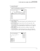
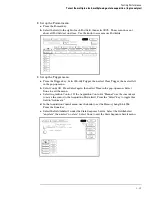
Configure the trigger according to the connected channels.
a
Press the Trigger key.
b
Select the field next to "a" under the label Bus1. Type the following for your logic
analyzer, then press the Select key.
Agilent 1670G – "AA"
Agilent 1672G – "AA"
Agilent 1671G – "2A"
Agilent 1673G – "0A"
5
5
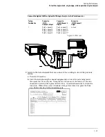
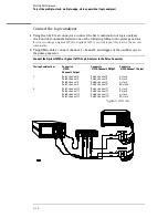
Enable the pulse generator channel 1, channel 2, and trigger outputs (with the LEDs
off).
Testing Performance
To test the single-clock, single-edge, state acquisition (logic analyzer)
3–22
Summary of Contents for 1670G Series
Page 20: ...1 12...
Page 116: ...Testing Performance Performance Test Record pattern generator 3 92...
Page 126: ...Calibrating and Adjusting To test the CAL OUTPUT ports 4 10...
Page 166: ...Exploded View of the Agilent 1670G series logic analyzer Replacing Assemblies 6 4...
Page 201: ...Theory of Operation The Oscilloscope Board 8 11...

