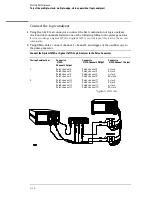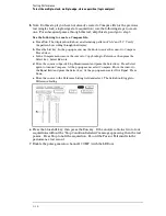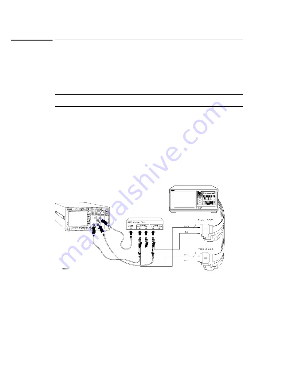
Connect the logic analyzer
1
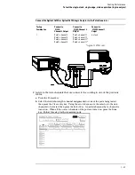
Using the 6-by-2 test connectors, connect the first combination of logic analyzer
clock and data channels listed in one of the following tables to the pulse generator.
If you are testing an Agilent 1670G or Agilent 1671G, you will repeat this test for the second
combination.
2
Using SMA cables, connect channel 1, channel 2, and trigger of the oscilloscope to
the pulse generator.
Connect the Agilent 1670G or Agilent 1671G Logic Analyzer to the Pulse Generator
Testing Combinations
Connect to
8133A
Channel 2 Output
Connect to
8133A Channel 2 Output
Connect to
8133A Channel 1 Output
1
Pod 1, channel 3
Pod 3, channel 3
Pod 5, channel 3
Pod 7, channel 3
Pod 2, channel 3
Pod 4, channel 3
Pod 6, channel 3
Pod 8, channel 3 *
J-clock
K-clock
L-clock
M-clock
2
Pod 1, channel 11
Pod 3, channel 11
Pod 5, channel 11
Pod 7, channel 11
Pod 2, channel 11
Pod 4, channel 11
Pod 6, channel 11
Pod 8, channel 11 *
J-clock
K-clock
L-clock
M-clock
*Agilent 1670G only.
Testing Performance
To test the multiple-clock, multiple-edge, state acquisition (logic analyzer)
3–32
Summary of Contents for 1670G Series
Page 20: ...1 12...
Page 116: ...Testing Performance Performance Test Record pattern generator 3 92...
Page 126: ...Calibrating and Adjusting To test the CAL OUTPUT ports 4 10...
Page 166: ...Exploded View of the Agilent 1670G series logic analyzer Replacing Assemblies 6 4...
Page 201: ...Theory of Operation The Oscilloscope Board 8 11...


