3
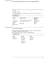
Set up the function generator according to the following table.
Function Generator Setup
Freq: 40.000 00 MHz
Amptd: 1.00 V
Modulation: Off
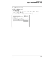
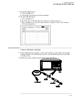
Connect the logic analyzer
1
Using a 6-by-2 test connector, connect channel 0 of Pod A1 to the pulse generator
channel 1 output.
2
Using the SMA cable and the BNC adapter, connect the External Input of the pulse
generator to the Main Signal of the function generator.
Testing Performance
To test the time interval accuracy (logic analyzer)
3–54
Summary of Contents for 1670G Series
Page 20: ...1 12...
Page 116: ...Testing Performance Performance Test Record pattern generator 3 92...
Page 126: ...Calibrating and Adjusting To test the CAL OUTPUT ports 4 10...
Page 166: ...Exploded View of the Agilent 1670G series logic analyzer Replacing Assemblies 6 4...
Page 201: ...Theory of Operation The Oscilloscope Board 8 11...

