13
Chapter 1: General Information
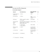
Recommended Test Equipment
Recommended Test Equipment
Equipment
Critical Specifications
Recommended Agilent
Model/Part
Use
†
Single-ended Flying Lead
Probe Set (Qty 2)
no substitute
E5383A
P, T
Ground Leads (Qty 5)
no substitute
pkg of 5
(Included with E5383A
Probe Set)
T
Pulse Generator
260 MHz,1 ns pulse width, two channels,
≤
150 ps rise time
8133A Option 003
P, T
150 ps Transition Time
Converter
(Qty 4)
Required if pulse generator’s rise time is less
than 150 ps (Voffset=1V,
∆
V=600 mV).
Required for 8133A opt. 003
Agilent or HP 15435A
P
Oscilloscope
≥
1.5 GHz bandwidth,
≥
8 GSa/s sampling rate
54845A or 54845B
P
SMA/Flying Lead Test
connectors
no substitute
See “To Assemble the
SMA/Flying Lead Test
Connectors” on page 22
P
2 x 9 Test connectors
no substitute
See “To Assemble the 2 x
9 Test Connectors” on
page 71
P
SMA Coax Cable (Qty 2)
≥
18 GHz bandwidth
8120-4948
P
†P = Performance Tests, T = Troubleshooting
Summary of Contents for 16900 Series
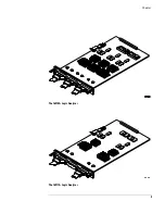
Page 3: ...3 Chapter The 16910A Logic Analyzer The 16911A Logic Analyzer...
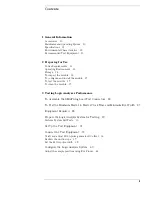
Page 8: ...8 Contents...
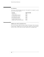
Page 14: ...14 Chapter 1 General Information...
Page 18: ...18 Chapter 2 Preparing for Use...
Page 61: ...61 4 Calibrating This chapter gives you instructions for calibrating the logic analyzer...
Page 65: ...65 Chapter 5 Troubleshooting Troubleshooting Flowchart 1...
Page 66: ...66 Chapter 5 Troubleshooting Troubleshooting Flowchart 2...
Page 82: ...82 Chapter 5 Troubleshooting To test the cables 18 Return to the troubleshooting flow chart...
Page 94: ...94 Chapter 7 Replaceable Parts 16910A Exploded View Exploded view of the 16910A logic analyzer...
Page 95: ...95 Chapter 7 Replaceable Parts 16911A Exploded View Exploded view of the 16911A logic analyzer...
Page 96: ...96 Chapter 7 Replaceable Parts...
Page 102: ...102 Index...

